24 C2908M-B (4/05)
Hardware Installation
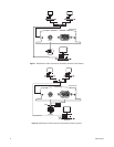
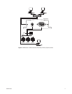
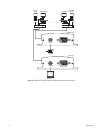
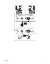
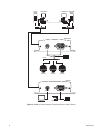
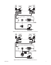
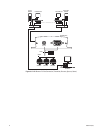
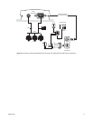
Refer to Appendix A — Connecting PelcoNet NET300 to Different Components for examples of how to connect equipment.
CONNECTING VIDEO SOURCES OR DISPLAYS
• The NET300 transmitter’s BNC Video In socket accepts color or black-white sources and automatically detects whether it is PAL or NTSC.
The video input has an internal termination of 75 ohms.
• The NET300 receiver’s BNC Video Out socket can be connected to any PAL or NTSC video monitor or VCR with a composite PAL or NTSC
input.
CONNECTING DATA TERMINALS
The bidirectional data interface port can be used to control equipment connected to the NET300 (for example, a dome camera with motorized
lens). The port supports RS-232, RS-422, and RS-485 asynchronous serial interfaces.
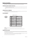
PIN ASSIGNMENTS
Table A.
Pin Assignments
CONNECTING AN ALARM
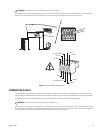
The NET300 has two alarm inputs. Input 1 lets you connect external signaling devices, such as a door contact. (Note that there is no motion
alarm on a NET300 receiver.) Input 2 has limited functionality in that it can only be used to establish a box-to-box connection to another NET300,
and only when the Connect On Alarm field is set to On.
If configured accordingly, an alarm trigger can also set up an automatic connection between the NET300 and the remote station. You can connect
switches or contacts directly without a separate power supply. The alarm inputs are N.O. (normally open).
Do the following to connect an external sensor. Refer to Figure 17.
Pin RS-232 RS-422/485
1 DCD (data carrier detect) –
2 RX (receive data) RX+ (receive data plus)
3 TX (transmit data) TX– (transmit data minus)
4 DTR (data terminal ready) –
5 GND (ground) GND (ground)
6 DSR (data set ready) –
7 RTS (ready to send) TX+ (transmit data plus)
8 CTS (clear to send) RX– (receiver data minus)
9– –
NOTE:
Transmission of transparent data is possible only when a video connection has been established.
WARNING:
Pay attention to documentation relating to the installation and operation of the equipment being controlled.
12345
6789


