C2908M-B (4/05) 25
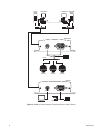
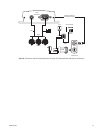
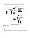
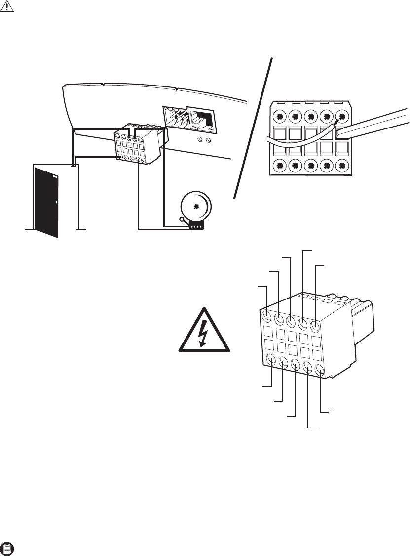
On the plug-in terminal block, attach conductors to the alarm input (IN1 and IN2) and ground conductor (GND) terminals. (Insert a small screw-
driver tip in the square hole and push hard enough to open the corresponding round hole. Insert the wire in the round hole.)
Figure 17.
Alarm and Relay Connections
CONNECTING A RELAY
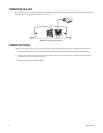
The NET300 has a relay for operating external devices (for example, a light or siren). The relay can be operated from a control page during an
active connection or automatically to coincide with certain events. Settings for the relay must be configured (refer to the Configuration section).
Do the following to connect a peripheral device (such as a light) that can be activated from a PelcoNet live video page.
Refer to Figure 17. On the plug-in terminal block, attach a wire conductor to each of the relay terminals (R). (Insert a small screwdriver tip in the
square hole and push hard enough to open the corresponding round hole. Insert the wire in the round hole.) It does not matter which conductor
wire goes to which relay terminal. The device the relay activates will need its own power supply.
WARNING:
The maximum rating of the alarm contact is 30 VDC and 8 mA.
WARNING:
The maximum rating of the relay contact is 30 VDC and 1 A.
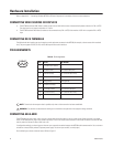
30 V
(POWER)
R (RELAY)
GND
GND
IN2 (ALARM INPUT2)
NOT USED
NOT USED
IN1 (ALARM INPUT1)
R (RELAY)
+ (POWER)


