C2908M-B (4/05) 79
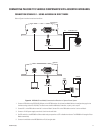
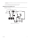
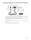
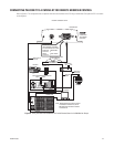
2. On the receiver side, connect TX− on the DB9 cable to terminal 7 on the wall block. Connect TX+ on the DB9 cable to terminal 8 on the wall
block. Connect RX− on the DB9 cable to terminal 2 on the wall block. Connect RX+ on the DB9 cable to terminal 1 on the wall block.
3. Connect a 12 VAC power supply to terminals 3 and 4 on the wall block.
4. Connect the wall block to the KBD4000 with an RJ-45 straight cable. (Note that DIP switches 4 and 8 on the KBD4000 must be set ON.)
5. Connect the monitor.
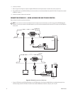
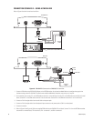
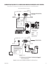
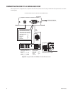
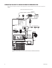
6. Refer to Figure 43 and Figure 45. Splice the supplied DB9 cable into the multiplexer wall block. Connect TX− from the NET300 transmitter
to terminal 2 on the wall block, TX+ to terminal 1, RX− to terminal 7, and RX+ to terminal 8.
7. Plug the DB9 cable into the RS232/422485 port on the transmitter. (In the Interface Mode field, select RS-422-485.) The data format must
be 9600, 8, odd, 1.
8. Connect the wall block to COM IN on the multiplexer with RJ-45 straight cable.
9. Connect MAIN video output from the multiplexer to the transmitter.


