


12 Pelco Manual C1995M-A (10/01)
CONNECTING CAMERAS
ALARMS
COM-IN
COM-OUT
12 VDC
1 2 3 4 H 0
OUT IN
SVHS
VCR
MAIN
SVHS75 OHMS
1234
SPOT
IN
OUT
1234
LOOPING INPUTS
LOOPED VIDEO
NON-LOOPING INPUTS
00154
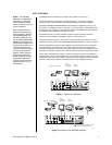
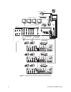
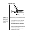
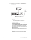
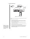
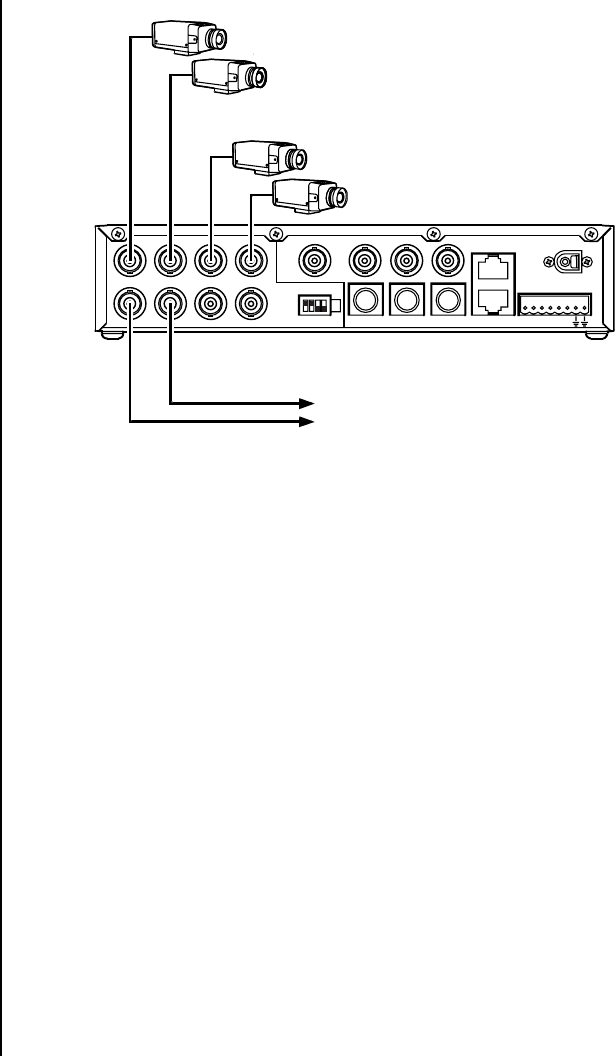
Figure 7. Camera Wiring Example
Video inputs can come from any conventional source. No external camera synchronization
is required. Table A shows the type of video coaxial cable to use.
To connect cameras (refer to Figure 7):
1. Connect the coaxial cables from your cameras or receivers to the IN connectors. If
you are using moveable cameras, the receivers must be Coaxitron compatible.
Stand-Alone Multiplexer – Connect fixed cameras to channel inputs.
Multiplexer with KBD4000/KBD4002/KBD4000V – Connect fixed or moveable
cameras to channel inputs.
Multiplexer with KBD4000/KBD4002/KBD4000V and MX4000SVR Server –
Connect fixed or moveable cameras to channel inputs.
Multiplexer with CM6700 – See step 2.
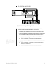
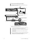
2. If you want to loop a video signal out to another device, connect coaxial cables from
the looping OUT connectors to the external equipment inputs. Termination for each
camera input at the multiplexer must be changed from 75 ohms to high impedance
through DIP switches on the rear of the multiplexer.
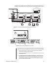
Multiplexer with CM6700 – Connect fixed or moveable cameras to the multiplexer
first, and then loop them to the CM6700 (refer to Figure 4). Termination for each
camera input at the multiplexer must be changed from 75 ohms to high impedance
through DIP switches on the rear of the multiplexer.
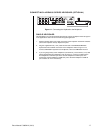
IMPORTANT:
Camera
power should be wired in
phase to all cameras. When
cameras are sequenced,
they will roll on the spot
monitor if they are out of
phase. On the main monitor,
cameras are digitally time
corrected and will not roll
when sequenced if they are
out of phase.