


Pelco Manual C1995M-A (10/01) 19
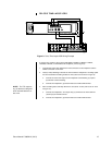
CONNECTING AN MX4000SVR SERVER WITH KEYBOARDS (OPTIONAL)
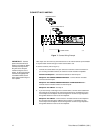
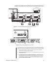
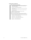
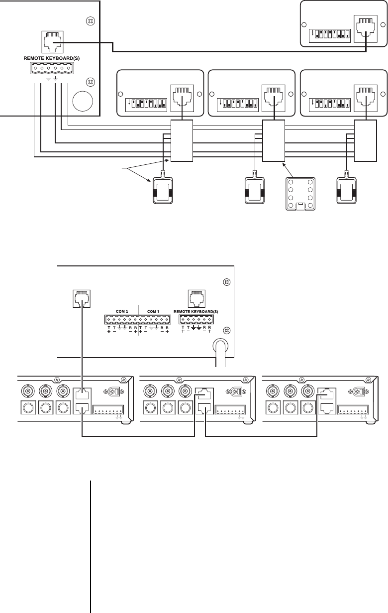
Figure 13. Connecting KBD4000/KBD4002 Keyboards to the Server
R+R-T-T+
LOCAL
KEYBOARD
ON
12345678
ON
12345678
ON
12345678
ON
12345678
1 TX+
2 TX-
3 12VAC
4 12VAC
5 GND
6NC
7 RX-
8 RX+
1 TX+
2 TX-
3 12VAC
4 12VAC
5 GND
6NC
7 RX-
8 RX+
1 TX+
2 TX-
3 12VAC
4 12VAC
5 GND
6NC
7 RX-
8 RX+
ADDRESS #2 (REMOTE)
CONTROLS MONITOR 2
ADDRESS #3 (REMOTE)
CONTROLS MONITOR 3
ADDRESS #4 (REMOTE)
CONTROLS MONITOR 4
ADDRESS #1 (LOCAL)
CONTROLS MONITOR 1
KBDKIT
MULTIPLEXER
WALL BLOCK
1
2
3
45
6
7
8
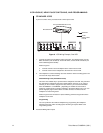
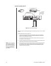
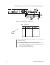
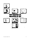
Figure 14. Daisy Chaining Multiplexers to the Server
LOCAL
KEYBOARD
MUX(S)
SERVER
MULTIPLEXER 1 MULTIPLEXER 2 MULTIPLEXER 3
ALARMS
COM-IN
COM-OUT
12 VDC
1 2 3 4 H 0
OUT IN
SVHS
VCR
MAIN
SVHS
ALARMS
COM-IN
COM-OUT
12 VDC
1 2 3 4 H 0
OUT IN
SVHS
VCR
MAIN
SVHS
ALARMS
COM-IN
COM-OUT
12 VDC
1 2 3 4 H 0
OUT IN
SVHS
VCR
MAIN
SVHS
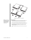
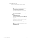
This installation is for up to four keyboards connected to a Genex MX4000SVR Multiplexer
Server. Refer to Figure 3 in the
Applications
section for an overview of a typical application.
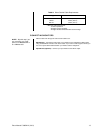
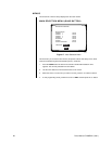
1. Remove the DIP switch cover plates on the backs of the keyboards. Set the DIP
switches (refer to Figure 14). Replace the plates.
2. Wire the keyboards as shown in Figure 13. To connect KBD4000V keyboards, refer to
the KBD4000V manual.
3. If you are going to daisy chain multiplexers (eight maximum), use the 6-foot (1.8 m)
data cables supplied with the multiplexers (refer to Figure 14). Connect a cable from
the first multiplexer’s COM OUT port to the second multiplexer’s COM IN port, then
connect the second multiplexer’s COM OUT port to the third multiplexer’s COM IN
port, etc. Continue to unit 8 if necessary.