


14 Pelco Manual C1995M-A (10/01)
VCR HOOKUP, HEAD PULSE SWITCHING, AND PROGRAMMING
STANDARD VCRS
If you have a Pelco VCR, proceed to Pelco’s Time-Lapse VCRs.
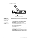
ALARMS
COM-IN
COM-OUT
12 VDC
1 2 3 4 H 0
OUT IN
SVHS
VCR
MAIN
SVHS75 OHMS
1234
SPOT
IN
OUT
1234
VCR (STANDARD OR SVHS)
RECORD/PLAY
GROUND
HEAD
SWITCHING
PULSE
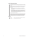
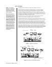
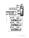
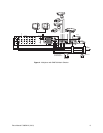
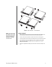
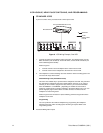
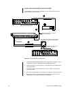
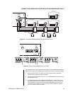
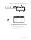
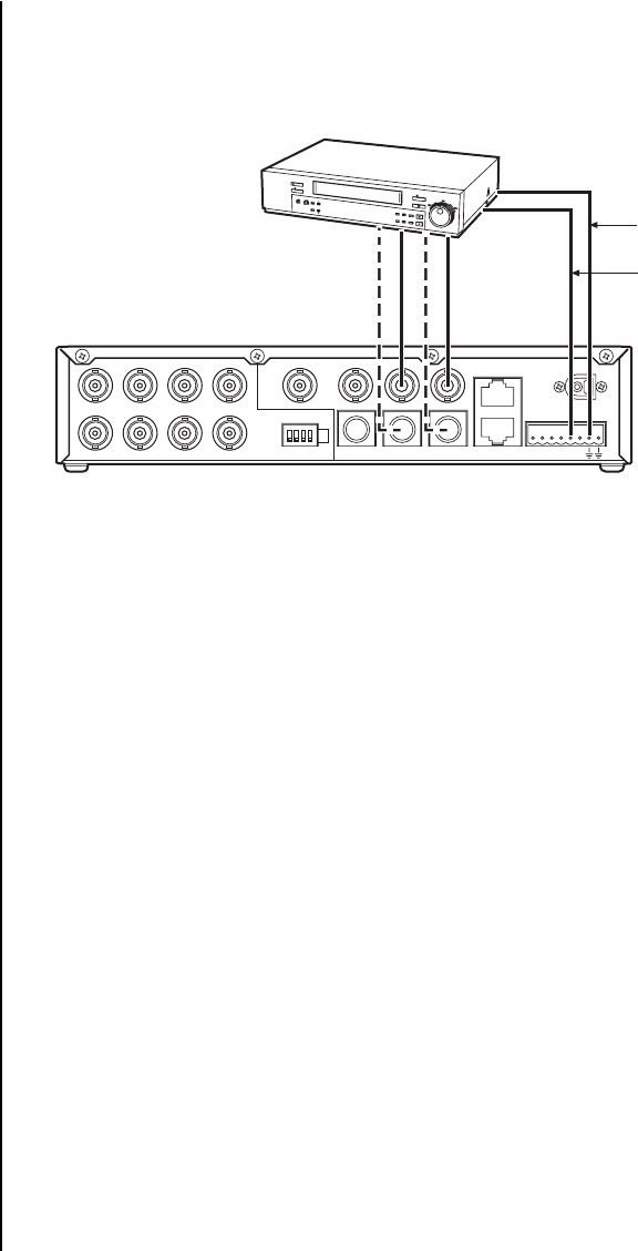
Figure 8. VCR Wiring Example, One VCR
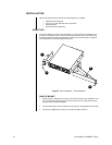
1. Connect the video to the multiplexer video connectors. For standard VCRs, use the
BNC connectors (refer to Table A). For SVHS VCRs, use the SVHS connectors (use
video cable designed for SVHS).
Refer to Figure 8.
a. Connect VCR OUT on the multiplexer to the video IN on the VCR.
b. Connect VCR IN on the multiplexer to the video OUT on the VCR.
2. The multiplexer’s camera switching rate must match the VCR’s recording speed. Use
one of the two ways shown below:
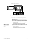
Head Switching Pulse (VCR Switch Pulse)
This is the most reliable way to synchronize the multiplexer and VCR. The pulse from
the VCR tells the multiplexer how fast to switch between cameras. (If you use this
method, you do not need to program the rate; however, you must set VCR Switch
Pulse to ENABLED + or ENABLED – [depending on whether the VCR sends a
positive or negative pulse to activate recording] in the Record Setup menu.) You can
pull the eight-pin plug-in terminal block out of the connector on the back of the
multiplexer to make wiring easier.
Refer to Figure 8 and connect the H (head switching) terminal and ground from the
multiplexer to the VCR.
Programming
You can synchronize the VCR and multiplexer by programming the multiplexer
switching rate to the VCR’s recording speed. No wiring is required. Refer to the
Programming
section.
Proceed to
Wiring Alarm Inputs
.