


16 Pelco Manual C1995M-A (10/01)
WIRING ALARM INPUTS
ALARMS
COM-IN
COM-OUT
12 VDC
1 2 3 4 H 0
OUT IN
SVHS
VCR
MAIN
SVHS75 OHMS
1234
SPOT
IN
OUT
1234
VCR (STANDARD OR SVHS)
VIDEO INPUT
CORRESPONDS
TO ALARM INPUT
GROUND
ALARM
RECORD
SIGNAL
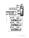
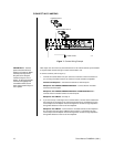
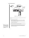
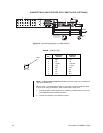
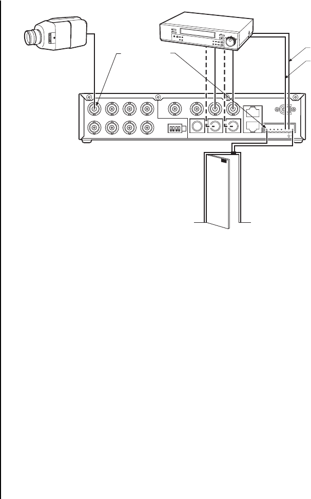
Figure 10. Alarm Wiring Example
Alarm inputs require a ground signal through a contact opening or closure, such as a switch
or relay.
To wire the alarm inputs (refer to Figure 10):
1. Connect one wire from the alarm source (for example, a door) to one of the alarm
input pins of the multiplexer. The alarm input must correspond to the camera input.
There is only one alarm input per camera.
You can pull the eight-pin plug-in terminal block out of the connector on the back of
the multiplexer to make wiring easier.
2. Connect a second wire from the alarm source to one of the ground connections on the
eight-pin plug-in terminal block on the back of the multiplexer.
3. If your VCR has an alarm input to change the VCR to its alarm recording speed when
the multiplexer receives an alarm, connect the VCR alarm input to the TTL output
relay (O) contact on the multiplexer. Connect a wire from the multiplexer’s ground
connection to ground on the VCR.
NOTE:
The TTL output re-
lay (O) terminal is designed
to be used with devices un-
der 5 mA. You can program
the relay as normally open
or normally closed through
the software.