


Pelco Manual C1995M-A (10/01) 15
PELCO’S TIME-LAPSE VCRS
ALARMS
COM-IN
COM-OUT
12 VDC
1 2 3 4 H 0
OUT IN
SVHS
VCR
MAIN
SVHS75 OHMS
1234
SPOT
IN
OUT
1234
PELCOTIME-LAPSE VCR
A
B
REMOTE
RESET
IN
GND
CLK
AUDIO
VIDEO
IN
OUT
CAL
OUT
OUT
MIC
ALM
IN
RECSET RST MODE
00137
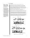
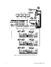
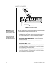
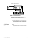
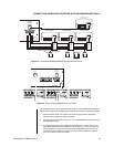
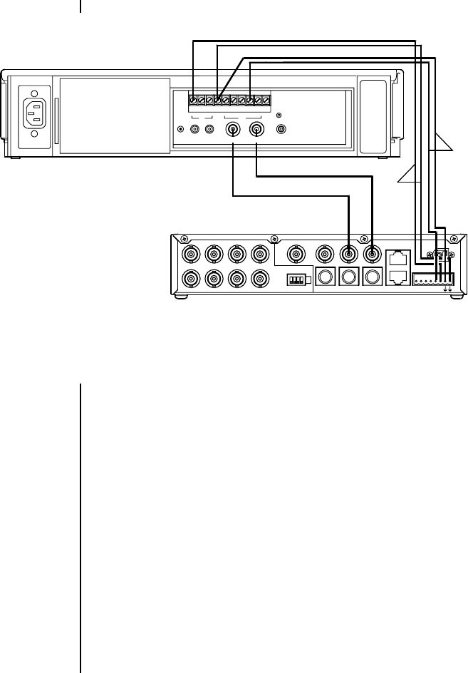
Figure 9. Pelco Time-Lapse VCR Wiring Example
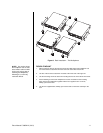
To connect one of Pelco’s Time-Lapse VCR Models TLR2024, TLR3024, TLR3040,
TLR2096, TLR2168, or TLR2168S to the multiplexer (refer to Figure 9):
1. Connect BNC video cable between the VCR connectors on the multiplexer and the
VIDEO connectors on the VCR.
2. Head (or VCR) Switching Pulse lets the VCR control the multiplexer’s recording speed.
It is the most efficient recording method. To wire (refer to the “B” lines in Figure 9):
a. Connect the VCR’s CLK output to the multiplexer head switching (H) input to
synchronize camera switching.
b. Connect the multiplexer’s ground terminal to the VCR’s GND terminal.
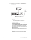
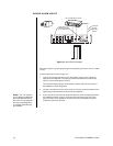
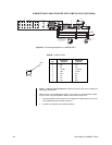
3. Alarm recording starts and stops when there are alarms. To wire (refer to the “A” lines
in Figure 10):
a. Connect the multiplexer’s TTL output relay (O) terminal to the VCR’s SET IN
(alarm input) or ALM IN terminal.
b. Connect the multiplexer’s ground terminal to the VCR’s GND terminal.
NOTE:
The TTL output re-
lay (O) terminal is designed
to be used with devices un-
der 5 mA.