15
Getting Started
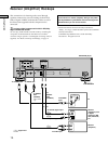
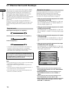
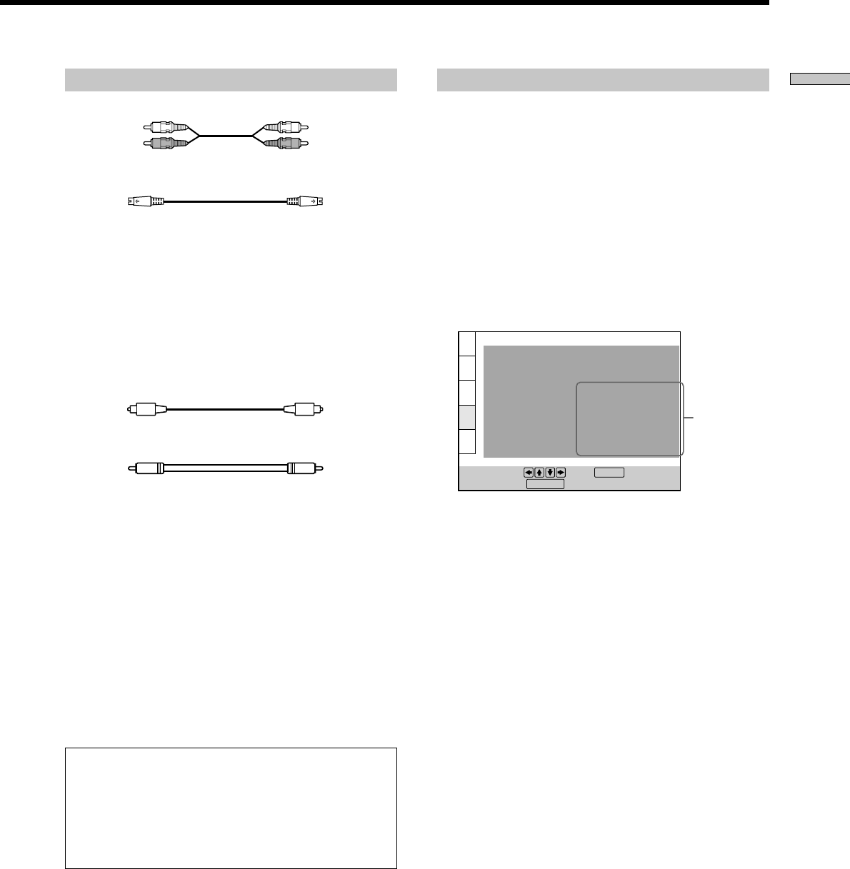
Required cords
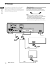
Audio connecting cord (not supplied) (1)
S video cord (supplied) (1)
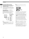
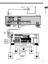
When connecting the cords, be sure to match the color-coded
cord to the appropriate jacks on the components: Red (right) to
Red and White (left) to White. Be sure to make connections firmly
to avoid hum and noise.
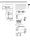
If you have a digital component such as a receiver (amplifier)
with a digital connector, DAT or MD, connect the component via
the DIGITAL OUT OPTICAL or COAXIAL connector using an
optical or coaxial digital connecting cord (not supplied).
Optical digital connecting cord (not supplied) (1)
Coaxial digital (75 Ω) connecting cord (not supplied) (1)
Notes
• You cannot enjoy a picture with an S video signal if your TV
does not conform to the S video signal. When your TV does
not have an S VIDEO input, connect the component via the
VIDEO INPUT connector using the audio/video connecting
cord (supplied) instead of the S video cord. For details, see
page 11.
Refer to the instructions supplied with your TV.
• You cannot make digital audio recordings of discs recorded in
multi-channel surround format directly using an MD deck or
DAT deck.
• SACD audio signals are not output from the DIGITAL OUT
OPTICAL or COAXIAL connectors.
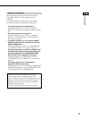
When you have made the connections using an optical or
coaxial digital connecting cord, do not set “DOLBY
DIGITAL” to “DOLBY DIGITAL,” “DTS” to “ON,” “MPEG” to
“MPEG” and “48kHz/96kHz PCM” to “96kHz/24bit.” If you
do, a loud noise will suddenly come out from the
speakers, affecting your ears or causing the speakers to be
damaged.
Setups for the player
Some setup adjustments are necessary for the player
depending on the components to be connected.
Use the setup display to change the various settings.
For details on using the setup display, see page 52.
• To listen to the sound through speakers connected
to a receiver (amplifier) which has a digital
connector and lacks a built-in DTS, Dolby Digital or
MPEG audio decoder, or to output the sound to a
digital component such as a DAT or MD deck
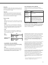
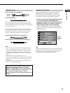
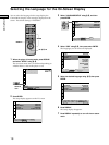
Set the “AUDIO SETUP” items in the setup display
(page 63) as shown in the illustration below. These are
the default settings.
Note
When you output the signals which do not reproduce the Dolby
Surround (Pro Logic) effect from the DIGITAL OUT OPTICAL or
COAXIAL connector, set “DOWNMIX” to “NORMAL” in
“AUDIO SETUP” in the setup display (page 63).
AUDIO SETUP
AUDIO ATT:
AUDIO DRC:
AUDIO FILTER
DOWNMIX
DIGITAL OUT:
To set, press , then .
To quit, press .
OFF
STANDARD
SHARP
DOLBY SURROUND
ON
ENTER
DOLBY DIGITAL:
DTS:
D-PCM
MPEG:
PCM
OFF
48kHz/96kHz PCM:
48kHz/16bit
DISPLAY
Set the
items as
shown
White (L)
Red (R)
White (L)
Red (R)


