


Understanding the Measurement Process
Whenever you make a basic measurement, there is a sequence of events that
you will go through. Referring back to this measurement process will help
you to better understand the exercises as you complete them.
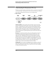
1 Map to target
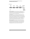
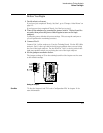
Connect probes Connect probes from the target system to the logic
analyzer to physically map the target system to the channels in the logic
analyzer. Attach probes to a pod in a way that keeps logically-related
channels together. Remember to ground the pod. For the logic analysis
lessons you will connect pods 1 and 3, for the oscilloscope lessons you
will also connect an oscilloscope probe, and for the pattern generator
lesson you will connect a pattern generator pod and TTL Data Pod to the
training board.
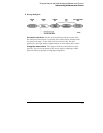
Set type The analyzer has three modes: the timing analyzer mode, the
state analyzer mode, and the system performance (SPA) mode. The
exercises in this training kit will teach you about the first two modes,
timing and state. The timing mode uses the clock within the analyzer
and the state mode uses the clock supplied by the target system. When
the logic analyzer is turned on, Analyzer 1 is named Machine 1 and is set
to timing mode, and Analyzer 2 is off. To use state analysis, you must set
the analyzer mode to state. You can use state and timing modes
together, but you can’t set both analyzer modes to timing.
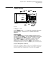
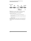
Assign pods In the Analyzer Configuration menu, assign the connected
pods to the analyzer you want to use. The number of pods on your logic
analyzer depends on the model. Pods are paired and are always assigned
as a pair to a particular analyzer.
Using the Analyzer and Understanding the Measurement Process
Understanding the Measurement Process
1–4