


Before You Begin
1 Decide what to do next.
If you have just completed the exercises in chapters 2 through 6, go to
"Connect the Channel 1 Oscilloscope Probe" on the next page.
If you have not just completed the exercises in chapters 2 through 6, go to
step 2.
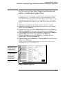
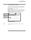
2
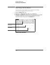
Load the configuration files CH07._A and CH07._B.
When loading these files, you must set the analyzer to load All, because you
are loading two types of files for this exercise. Setting the analyzer to load
Analyzer like you did in previous exercises, will only load CH07._A properly.
The files will default all system and oscilloscope settings. If you need
instructions to load the configuration files, refer to chapter 11, "To Load a
Configuration File."
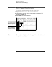
3
Connect Pod 1.
Connect Pod 1 of the analyzer to J1 on the Training Board. For the
HP 1660s, Pod 1 is the top cable in the left-most position when you are facing
the rear of the logic analyzer. Pod 1 must be connected in order to supply
the +5 V power for the training board.
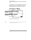
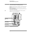
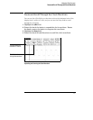
4
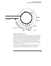
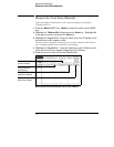
Set the jumpers as shown below.
The jumper settings of J5 on the training board for this chapter are the same
as the default settings. For more information about setting the jumpers, refer
to chapter 11, "To Set the Jumpers."
CLK2
GLITCH
P. G.
OSC
CLK2
OFF
ON
CLK1
P. G.
Using the Oscilloscope
Before You Begin
7-3