


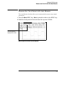

Connect the Channel 1 Oscilloscope Probe
1 Connect the oscilloscope probe to channel 1 on the front panel of the
analyzer.
2 Connect the probe tip to the test point labeled "CLK 1" on the Logic
Analyzer Training Board.
3 Connect the probe ground lead to the test point labeled "GND" on the
Logic Analyzer Training Board.
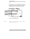
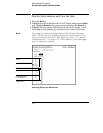
Note Connect pod 1 to J1 of the training board. Pod 1 must be connected to
supply the +5 V power for the training board.
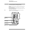
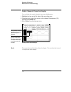
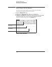
Connecting the Channel 1 Oscilloscope Probe
GND - Oscilloscope
ground connects here.
J1 - Pod 1 of the
analyzer connects
here.
J5 - Jumpers are set
here.
CLK1 - Oscilloscope
probe tip connects here.
Using the Oscilloscope
Connect the Channel 1 Oscilloscope Probe
7-4