


Before You Begin
Note If your logic analyzer is an HP 1663 or HP 1664 you cannot perform
these exercises. The HP 1663 and HP 1664 have 32 data acquisition
channels on two pods. All 32 channels may be assigned to either state
or timing analysis, but they cannot be separated to perform mixed-mode
measurements.
1
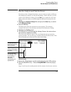
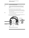
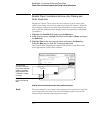
Set the jumpers as shown below.
The jumper settings of J5 on the training board for this chapter are the same
as the default settings.
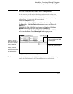
2 Decide what to do next.
If you have just completed all of the exercises in chapters 2 through 4, go to
"Connect the Timing Analyzer" on the next page.
If you have not just completed all of the exercises in chapters 2 through 4, go
to step 3.
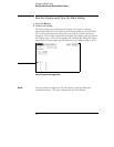
3
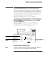
Load the Analyzer with the configuration file, CH05._A.
The file will default all system settings and then set up the analyzer as if you
had just completed all of the exercises in chapters 2 through 4.
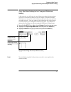
Unless you are using an HP 1661 or an HP 1671 analyzer, you may see an
advisory message when you load the files. This is not an error. The message
is displayed because these logic analyzers have a different number of data
pods from the HP 1661, which was used to create the files.
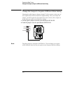
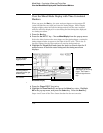
4
Connect Pod 1.
Connect Pod 1 of the analyzer to J1 on the Training Board. For the
HP 1660s, Pod 1 is the top cable in the left-most position when you are facing
the rear of the logic analyzer. For the HP 1670s, Pod 1 is the top cable in the
right-most position when you are facing the rear of the logic analyzer.
See Also "To Set the Jumpers" and "To Load a Configuration File" in chapter 11 for
more information.
CLK2
GLITCH
P. G.
OSC
CLK2
OFF
ON
CLK1
P. G.
Mixed Mode - Correlation of State and Timing Data
Before You Begin
5-3