


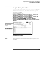

Connect the Oscilloscope Probe
1 Connect the oscilloscope probe to channel 1 on the front panel.
2 Connect the probe tip to the test point labeled "Glitch" on the Logic
Analyzer Training Board.
Note that this is a different test point than the "CLK 1" test point that was
used in Chapter 7.
3
Connect the probe ground lead to the test point labeled "Ground" on
the training board.
Note Leave Pod 1 connected to J1. This provides +5 V for the training board.
If Pod 1 is not connected to J1, connect it now.
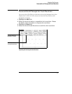
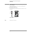
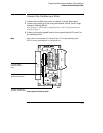
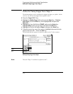
Connecting the Oscilloscope Probe
GND - Oscilloscope
ground connects here.
GLITCH - Oscilloscope
probe tip connects here.
J1 - Pod 1 of the
analyzer connects
here.
Triggering the Oscilloscope with the Timing Analyzer
Connect the Oscilloscope Probe
8-5