


Introduction to Timing Analysis
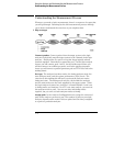
Timing analysis in its simplest form means acquiring and storing data
at equal time intervals. When doing timing analysis you must put the
logic analyzer into timing mode. An analyzer in timing mode is
referred to as a timing analyzer. The timing analyzer’s time interval is
controlled by a clock inside the analyzer, just like the clock in a
digitizing oscilloscope. However, there are key differences between a
timing analyzer and a digitizing oscilloscope. These key differences
are channel count and voltage resolution. A logic analyzer typically
has a large number of channels, and it displays signals at only two
voltage levels, a logic high or a logic low. A digitizing oscilloscope
typically has fewer channels, but it can display signals with much finer
voltage resolution.
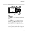
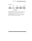
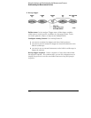
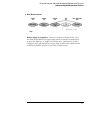
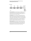
To determine whether a given sample of data should be stored and
displayed as a logic high or a logic low, the timing analyzer compares
the data to a threshold voltage. The threshold voltage works just like
the threshold voltage in logic circuits. If the voltage level of the
sampled data is above the threshold, the analyzer stores a logic high
(a "1"). If the voltage level of the data is below the threshold, the
analyzer stores a logic low (a "0").
The exercises in this chapter step you through the process of making
a timing measurement.
In this chapter, you will:
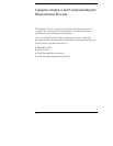
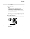
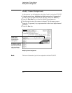
• Put the analyzer into timing mode
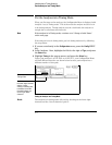
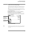
• Change a label name
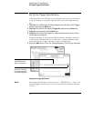
• Modify channel assignments
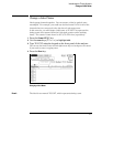
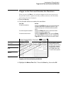
• Define a term for the timing trigger
• Set up the trigger specification
• Trigger on the term and examine the waveform
2-2