


13
Connecting the RS-422/485
Connecting the RS-422/485
Device
Device
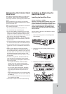
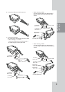
This DVR has two data terminals.
Use this port to connect PTZ cameras, DVRs or key-
pads (optional).
Example, when the PTZ camera is connected.
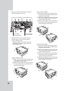
1. Connecting the PTZ serial communication lines to
terminal block.
2. Connecting the terminal block to the RS-422/485
terminal.
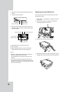
Notes:
• When connecting lines, connect the TX - of the
DVR to RX - of the PTZ unit and TX + of the DVR
to RX + of the PTZ unit correctly.
• Recommended initial data are 9600 Baud Rate,
8 Data bits, 1 Stop bit and No parity.
• When connecting PTZ cameras to DVRs it is
necessary to set the setup menu for this unit
according to the RS-485 settings of the camera
and DVRs.
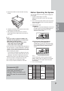
Connecting Sensor Input and
Connecting Sensor Input and
Alarm Output
Alarm Output
Alarm terminals are used to connect the alarm
devices such as sensors, door switches, etc.
Sensor Input
Connect up to 16 alarm sensors (LDV-S503: 8 alarm
sensors) using the terminal blocks.
Each alarm sensor should be connected with G (GND).
The signal state is adjustable to N/O (Normal Open)
or N/C (Normal Close) through the setup menu.
HOOKUP AND
SETTINGS
PTZ Units
(RS-422/485 TYPE)
RX- RX+ RX- RX+
RX- RX+ RX- RX+
PTZ Units
(RS-422/485 TYPE)
5~7 mm
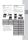
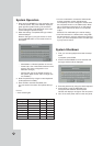
SENSOR-IN
Terminal No. Description
1 Sensor Input 1
2 Sensor Input 2
3 Sensor Input 3
4 Sensor Input 4
G Ground
5 Sensor Input 5
6 Sensor Input 6
7 Sensor Input 7
8 Sensor Input 8
G Ground
9 Sensor Input 9
10 Sensor Input 10
11 Sensor Input 11
12 Sensor Input 12
G Ground
13 Sensor Input 13
14 Sensor Input 14
15 Sensor Input 15
16 Sensor Input 16
G Ground
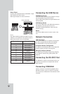
RS-422/485 Terminal Description
TX - (DATA -) Data Transmission
TX + (DATA +) Data Transmission
RX - (DATA -) Data Reception
RX + (DATA +) Data Reception
GND Shield
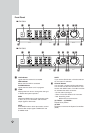
Rear of the DVR
Rear of the DVR