


10
Parts and their functions (continued)
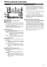
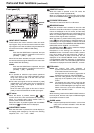
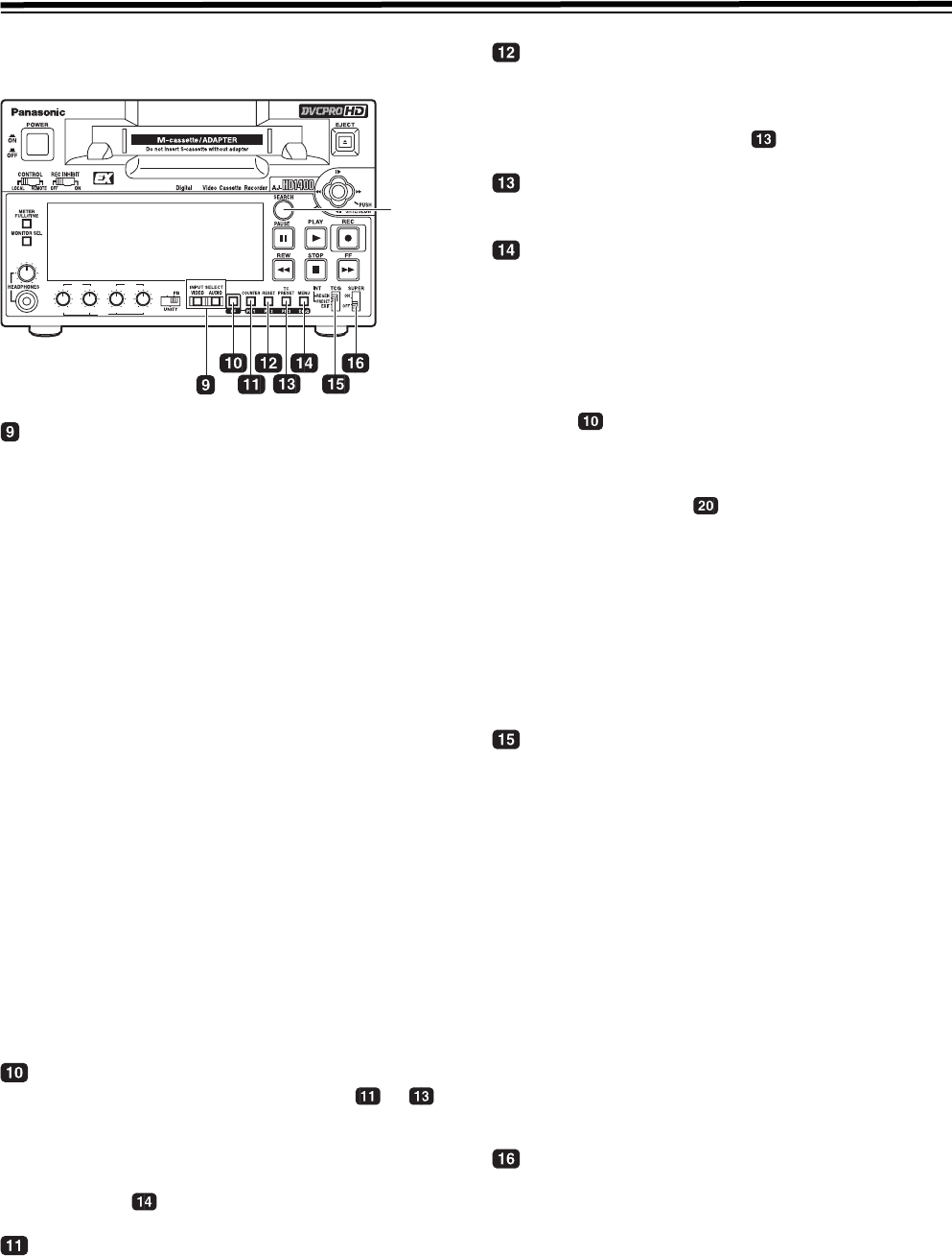
Front panel (2)
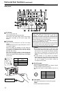
INPUT SELECT buttons
These buttons are used to switch the video and audio
input signals. They can also be used to switch the video
input signals to the internal reference signal selected as
the menu item No.601 VIDEO INT SG setting.
VIDEO:
Each time the VIDEO button is pressed, the input
video signal selection is switched in the order of
[HD SDI] > [1394] > [SG].
When SG has been selected, the signal is switched to
the internal reference signal selected as the menu item
No.601 VIDEO INT SG setting.
AUDIO:
Each time the AUDIO button is pressed, the input
audio signal selection is switched in the order of
[HD SDI] > [SG] > [ANALOG].
<Notes>
z It is possible to inhibit the input switch operations
(video and audio) of the INPUT SELECT buttons
using menu item No.190 V IN SEL INH and item
No.191 A IN SEL INH.
z The audio input signal cannot be switched to [1394]
independently. The audio signal can be switched to
[1394] only when the video signal is switched to
[1394] by interlocking.
Since the audio input signal at this time is fixed to
[1394], it cannot be switched to another input signal.
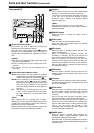
PF button
When this button is pressed, buttons - to
function as the PF1, PF2 and PF3 buttons, respectively.
When it is pressed again before another button is
pressed, these modes are canceled.
When this button is pressed together with the MENU/
DIAG button , the DIAG screen is displayed.
COUNTER/PF1 button
Each time this button is pressed, the counter display on
the display panel changes by one step in the following
sequence: CTL > TC > UB > REM.
RESET/PF2 button
When this button is pressed in the CTL mode, the
counter display is reset to [00:00:00:00].
When it is pressed in the TC/UB mode while holding
down the TC PRESET button , the generator is reset.
TC PRESET/PF3 button
This button is used to set the TC or UB values.
MENU/DIAG button
When the connector that is selected in menu No. 005
SUPER is used, When this button is pressed, the setup
menus are displayed on the TV monitor, and the setup
menu numbers are displayed on the unit’s display panel.
When it is pressed again, the setup menu settings are
exited, and the original status is restored.
When the button is pressed while holding down the PF
button , the VTR information is displayed. When it is
pressed again, the original display is restored. The VTR
information consists of the WARNING, HOURS METER,
UMID INFO and DIF STATUS 1, 2 information.
The SEARCH button is used to switch the displays
between these kinds of information.
Descriptions of the warnings are displayed on the
WARNING screen. The deck’s serial number, poweron
time, drum rotation time, tape travel time, number of
loading times, number of power on/off times, etc. are
displayed on the HOURS METER screen. The UMID
(Unique Material Identifier) information is displayed on
the UMID INFO screen. The IEEE1394 digital interface
information is displayed on the DIF STATUS 1, 2 screen.
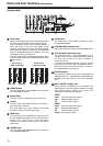
TCG switch
REGEN
: The internal time code generator is
synchronized with the time code which the time
code reader has read from the tape.
The signal that is to be used for regeneration is
selected using menu No. 505 TCG REGEN.
PRESET
: The time code generator can be preset (see
page 55) on the operation panel or by remote
control.
EXT: The external time code which is input from the
time code input connector or video signal SLTC,
SVITC or IEEE1394 digital input signal is used.
Which of the two is to be set is selected using
menu No. 507 EXT TC SEL.
<Note>
When selecting “1394” with the INPUT VIDEO switch on
the front panel, the time code input to IEEE1394 digital
input/output connector is used.
SUPER switch
ON: Outputs superimposed information, such as time
code, to the connector selected in menu No. 005
SUPER.
OFF: No superimposed information is output.
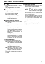
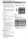
REC/PB
CH1/5 CH2/6
CH3/7 CH4/8
REC
PB
CH1 CH2 CH1 CH2
PB
HD
SEARCH
button