


45
Setup menus (continued)
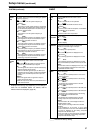
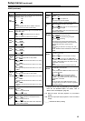
TAPE PROTECT
“_____” indicates the factory setting.
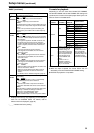
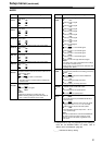
TIME CODE
*1 Displayed menus may vary depending on the settings in
menu No. 25 SYSTEM FREQ. For details, refer to
“Menus which are displayed” (page 32).
*2 Even if the RESET button is pressed while pressing the
SEARCH button, the value may not return to the factory
setting.
No./Item Description of setting
400
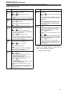
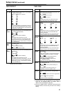
STILL TIMER
For setting the time to be taken before the unit is set
in the tape protection mode when it is left standing in
the STOP or STILL status.
(Units: S = seconds, min = minutes)
0000 0.5S
0001 5S
0002 10S
0003 20S
0004 30S
0005 40S
0006 50S
0007 1min
0008
2min
<Note>
When a DV, DVCAM or an unused tape is used, or a
DVCPRO HD/DVCPRO50/DVCPRO tape is used in
the EE mode, any setting above 2 (10S) will result in
a setting time of 10 seconds.
401
SRC
PROTECT
For setting the operation to be performed in the tape
protection mode when the unit is left standing in the
STILL status (JOG/VAR/SHTL).
0000 STEP :
STEP FWD
0001 HALF :
STANDBY OFF (HALF LOADING)
<Note>
When STEP FWD is selected, the unit is
automatically transferred to the standby OFF (half
loading) mode when the unit is left standing in the
STOP mode for a total of 30 minutes (or 1 minute for
DV or DVCAM tape).
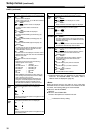
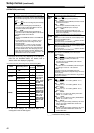
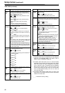
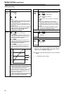
402
DRUM
STDBY
For setting the cylinder operation in the standby OFF
(half loading) mode.
0000 OFF
The cylinder stops rotating.
0001 ON
The cylinder continues to rotate.
403
STOP
PROTECT
For setting the operation to be performed in the tape
protection mode when the unit is left standing in the
STOP status.
0000 STEP :
STEP FWD
0001 HALF :
STANDBY OFF (HALF LOADING)
<Note>
When STEP FWD is selected, the unit is
automatically transferred to the standby OFF (half
loading) mode when the unit is left standing in the
STOP mode for a total of 30 minutes (or 1 minute
for DV or DVCAM tape).
No./Item Description of setting
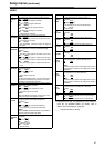
500*
1
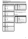
VITC BLANK
For setting whether to output the VITC signal at the
position which is set using menu items No.501 VITC
POS-1 and No.502 VITC POS-2.
0000 BLANK :
The VITC signal is not output.
0001 THRU :
The VITC signal is output.
<Note>
This setting takes effect only with the SD output
(analog composite output and SD SDI output).
501*
1
*
2
VITC POS-1
For setting the position where the VITC signal is to be
inserted.
<525 mode> <625 mode>
0000 10L 0000 7L
: : : :
0006
16L 0004 11L
: : : :
0010 20L 0015 22L
<Notes>
z The same line as the one selected by menu item
No.502 VITC POS-2 and No.692 UMID POS
cannot be selected.
z This setting takes effect only with the SD output
(analog composite output and SD SDI output).
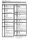
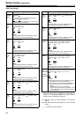
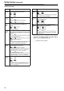
502*
1
*
2
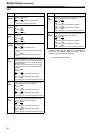
VITC POS-2
For setting the position where the VITC signal is to be
inserted.
<525 mode> <625 mode>
0000 10L 0000 7L
: : : :
0008
18L 0008 13L
: : : :
0010 20L 0015 22L
<Notes>
z The same line as the one selected by menu item
No.501 VITC POS-1 and No.692 UMID POS
cannot be selected.
z This setting takes effect only with the SD output
(analog composite output and SD SDI output).
503*
1
TCG MODE
For setting the synchronization of the internal time
code generator.
0000 SW :
When the TCG switch on the front panel is set to
REGEN or PRESET, the selection is complied.
0001 AUTO :
REGEN or PRE is automatically selected
depending on the operation mode.
When editing (including a chained shot):
REGEN is selected.
Other than the above: PRE is selected.
504*
1
RUN MODE
For setting the operation mode in which the internal
time code generator runs.
0000 REC :
The generator runs only while recording is in
progress.
0001 FREE :
The generator runs while the power is on
regardless of the unit’s operation mode.
505*
1
TCG REGEN
For setting the signal to be regenerated when the
TCG (time code generator) is in the regeneration
mode.
0000 TC&UB :
Both the time code and user bits are regenerated.
0001 TC :
Only the time code is regenerated.
0002 UB :
Only the user bits is regenerated.