


15
Parts and their functions (continued)
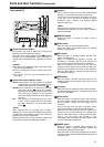
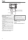
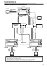
VIDEO OUT (1, 2, Y, PB, PR) connectors
By changing the menu item No.615 V OUT SEL setting,
either analog composite signals or HD analog
component Y signals are output from the VIDEO OUT1
connector.
Analog composite signals with superimposed information
embedded can be output from the VIDEO OUT2 connector.
Whether superimposed information is to be embedded
in the signals is selected using menu item No.005
SUPER.
<Note>
When HD analog component output or HD SDI output
signals are output with the 60 Hz or 24 Hz system
frequency, the SD SDI signals will be output without the
sync signals (NO SYNC), and the analog composite
signals will be output in the black-and-white mode (burst
OFF).
TC IN connector
This is used to record an external time code onto the
tape.
TC OUT connector
This is used to output the playback time code during
playback.
During recording, the time code generated by the
internal time code generator is output from this
connector.
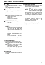
HD/SD REF VIDEO IN connector and OUT
connector
Input connector for the HD/SD reference video signal
and loop through output connector.
<Notes>
z When inputting an HD reference signal to the
connector, input a tri-level sync signal with positive
and negative polarities. Also, supply signals matching
the input signals and tape format.
z When inputting an SD reference signal to the
connector, use a black burst signal which satisfy the
SMPTE170M or ITU624-4 standard.
z If no cable is connected to the REF VIDEO OUT
connector, the REF VIDEO IN connector will be 75
h
automatically. If the cable is connected, the 75 h
connection is cancelled.
AUDIO IN connectors (CH1, CH2)
These are the input connectors for the analog audio
signals.
AUDIO OUT/MONITOR connector
(CH1, CH2, Lch, Rch)
These are the output connectors for the analog audio
signals.
It is possible to interlock Lch/Rch to the volume control
knob for headphones by adjusting menu No. 712 MONI
OUT appropriately.
AUDIO MONITOR connectors
These are the audio monitor output connectors.These
connectors output the monitor selection channels.
It is possible to interlock these connectors to the volume
control knob for headphones by adjusting menu No. 712
MONI OUT appropriately.
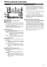
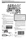
REMOTE CONTROL connector
An external remote controller is connected here to
enable the unit to be operated using an external device.
<Notes>
z Set the LOCAL/REMOTE switch to REMOTE.
z The connector satisfies the RS-422A interface
standard.
Fan motor
This is provided to cool off the unit.
Grips
This is the handle for carrying the unit.
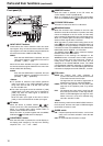
ENCODER REMOTE connector
Connect a connector encoder remote controller when
externally adjusting each setting of the video output signal.
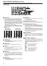
HD SERIAL COMPONENT AUDIO VIDEO IN/
OUT connector
These are input-output connectors for the HD digital
component audio/video signal conforming to the
SMPTE 292M, 296M or 299M standard.
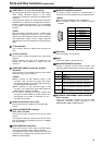
Pin No. Signal
1 FRAME GROUND
4 REM(G)
7
REM RX (X)
REMOTE CONTROL PROTOCOL RECEIVE
8
REM TX (X)
REMOTE CONTROL PROTOCOL TRANSMIT
14
REM RX (Y)
REMOTE CONTROL PROTOCOL RECEIVE
15
REM TX (Y)
REMOTE CONTROL PROTOCOL TRANSMIT
1
6
9
5
Pin No. Signal
1 Frame Ground
2 Transmit A
3 Receive B
4 Receive Common
5–
6 Transmit Common
7 Transmit B
8 Receive A
9 Frame Ground