


14
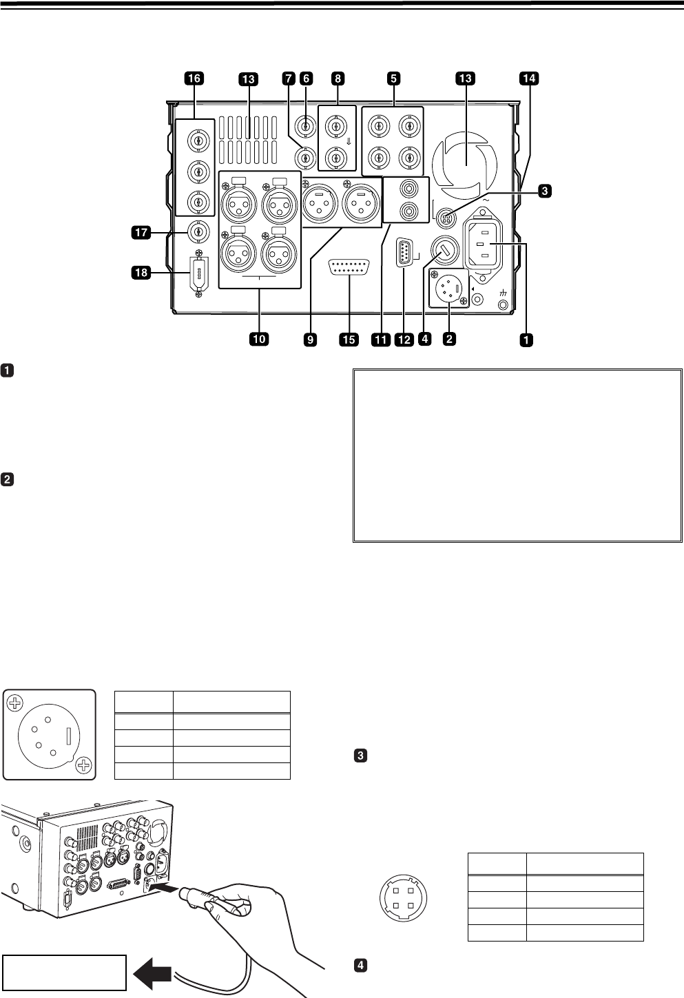
Parts and their functions (continued)
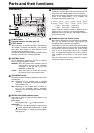
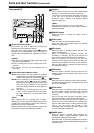
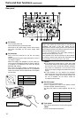
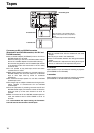
Rear panel
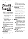
AC IN inlet
This is the AC power inlet.
Connect the accessory power cable here.
When both an AC power supply and DC power supply
have been connected, the AC power supply takes
priority.
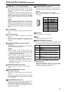
DC IN socket
This is the input connector for the DC 12V supply
voltage.
Use an external DC power supply rated at DC 12 V/7 A
(12 A peak or higher)
When the voltage has dropped to around 10.6V, the
unit’s power is automatically turned off. (When “TYPE-A”
or “TYPE-B” is not selected as the menu item No.180
BATTERY SEL setting)
Even when the supply voltage is restored later, the
power will not automatically come back on. The POWER
switch must be set to OFF and then back to ON several
seconds later.
<Notes>
z If an external DC power supply is used, then make
sure that the external DC power supply is first turned
ON, then this unit is turned ON. Improper operation
may result in a malfunction in the unit due to slow
startup of the output voltage of the external DC power
supply.
z If input exceeds 18 V by mistake, the protection
feature shuts down the power source at around 20 to
35 V. Change the voltage to the regular voltage, and
the unit is available. An AC source cannot be
connected to this terminal.
DC OUT socket
This is the DC 12V output socket.
Power is supplied from here to the external remote
controller (AJ-A95: optional accessory).
The DC power cable is packed together with the AJ-
A95.
Fuse holder
This holds the AC 250 V/2.5 A fuse (time lag type).
<Note>
Use the fuse specified by Panasonic.
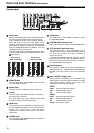
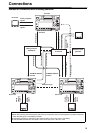
ENCODER
REMOTE
HD/SDI
IN
OUT1
OUT2
SD/SDI
DVCPRO
/DV
MONITOR
L
CH1
CH2
R
AUDIO OUT
OUT
IN
TC
HD/SD REF IN
AUDIO IN
CH1
CH2
VIDEO OUT
Y
1
2
P
B
P
R
AUDIO
MON
OUT
(SUPER)
L
R
DC OUT
FUSE 250V T2.5AH
F1
AC IN
DC IN
R
E
M
O
R
T
PUSH
PUSH
PUSH
PUSH
12V 250mA
SIGNAL
GND
1
2
3
4
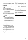
Pin No. Signal
1 Ground
2–
3–
4 +12 V
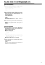
External DC adapter
If an external DC power supply is used, then check the
ratings of the external DC power supply so that they are
compatible with those of this unit. Check the pin
arrangements of the DC output terminal of the external DC
power supply and those of the DC IN socket of this unit so
that their polarities are correctly arranged.
If +12 V are supplied to the unit’s GND terminal by
mistake, this may cause fire or injury.
If the polarities of the DC IN connectors of other devices
are incorrect, and the other devices are connected to the
unit by mistake, fire or personal injury may result.
3
1
2
4
Pin No. Signal
1 Ground
2–
3–
4 +12 V