


47
Setup menus (continued)
VIDEO
*1 Displayed menus may vary depending on the settings in
menu No. 25 SYSTEM FREQ. For details, refer to
“Menus which are displayed” (page 32).
“_____” indicates the factory setting.
No./Item Description of setting
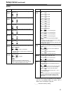
601*
1
VIDEO INT
SG
For selecting the type of internal standard signals.
0000 100%CB :
A 100% color bar signal is selected.
0001 75%CB :
A 75% color bar signal is selected.
0002 SMPTE :
An SMPTE color bar signal is selected.
0003 ARIB :
An ARIB color bar signal is selected.
0004 BLACK :
A black signal is selected.
602*
1
SDI IN MODE
For selecting how to process the serial input.
0000 DR_OFF :
The 8 higher bits whose two lower bits have been
rounded off are recorded.
0001 DR_ON :
The dynamically rounded 8 higher bit signal is
recorded.
603
V-MUTE SEL
For setting whether to mute the video output signal
when a blank part of the tape is detected during
playback.
0000 N-MUTE :
The video output signal is not muted. (It is frozen.)
0001 GRAY :
The video output signal is muted and turned gray.
0002 BLACK :
The video output signal is muted and turned black.
0003 NOISE :
The video output signal is muted and turned into
noise.
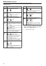
604
FREEZE SEL
For selecting the freeze mode of the still pictures and
the slow play mode.
0000 FIELD :
Field freeze, field slow
0001 FRAME :
Frame freeze, frame slow
<Note>
For IEEE 1394 digital output, if format conversion is
not executed, the frames may freeze or slow down
regardless of the settings in this item.
615*
1
V OUT SEL
For selecting what signals are to be output from the
VIDEO OUT1 output connector.
0000 CMPNT :
The HD component signals are output.
0001 CMPST :
Composite signals are output.
<Note>
When the CMPST is selected, the Pb and Pr of the
analog HD component signals are muted.
619*
1
V_FILTER
This is used to select the method to process the
images using the vertical filter during down-
conversion.
0000 FIELD :
The images are processed by field basis.
0001 FRAME :
The images are processed by frame basis.
<Note>
When “FRAME” has been selected, the resolution is
improved, but the images may flicker.
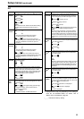
620*
1
DOWNCON
MODE
For setting the image processing during down-
conversion.
0000 FIT_V :
Side cut mode
0001 FIT_H :
Letter-box mode
0002 FIT_HV :
Squeeze mode
No./Item Description of setting
621*
1
UPCONV
MODE
For setting the image processing during up-
conversion.
0000 FIT_V :
Side panel mode
0001 FIT_H :
Top and bottom cut-off in vertical direction
0002 FIT_HV :
Stretch mode
626*
1
D/C ENH H
For enhancing the horizontal outlines during down-
conversion.
0000 0dB
0001
+1dB
627*
1
D/C ENH V
For enhancing the vertical outlines during down-
conversion.
0000 0dB
0001
+1dB
628*
1
U/C ENH H
For enhancing the horizontal outlines during up-
conversion.
0000 0dB
0001
+1dB
629*
1
U/C ENH V
For enhancing the vertical outlines during up-
conversion.
0000 0dB
0001
+1dB
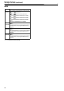
630*
1
1080i
>
HD_OUT
For selecting the HD output signal format during
1080i tape playback or in the 1080i EE mode.
0000 1080i
0001 720p
<Note>
This item’s setting cannot be changed while a tape is
being recorded or while the recording pause mode is
established.
632*
1
720p
>
HD_OUT
For selecting the HD output signal format during 720p
tape playback or in the 720p EE mode.
0000 1080i
0001
720p
<Note>
This item’s setting cannot be changed while a tape is
being recorded or while the recording pause mode is
established.
636*
1
SD
>
HD_OUT
For selecting the HD output signal format during SD
tape (DVCPRO50, DVCPRO, DV or DVCAM)
playback.
0000 1080i
0001 720p
650
STYLE
0000 CMPNT :
Level adjustment mode for the component style
0001 CMPST :
Level adjustment mode for the composite style