


46
Setup menus (continued)
TIME CODE (continued)
*1 Displayed menus may vary depending on the settings in
menu No. 25 SYSTEM FREQ. For details, refer to
“Menus which are displayed” (page 32).
*A The SBC (Sub Code Data) area is an area that exists
separately from the video and audio area on the helical
track and contains the tape management information,
such as the time code, in compliance with the SMPTE/
EBU and the recording time. As with the ordinary LTC
(Linear Time Code), the time code can be read even
when rewinding/fast-forwarding and can be read out
when the tape stops.
*B The VAUX (Video Auxiliary Data) area is an area in the
video area on the helical track and contains information
related to the video data.
“_____” indicates the factory setting.
No./Item Description of setting
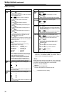
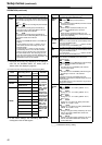
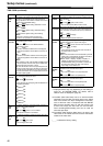
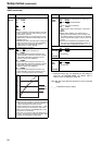
506*
1
REGEN
MODE
For selecting the editing mode range when the VTR is
operating in the REGEN mode while performing
editing operations with “AUTO” selected as the menu
item No.503 TCG MODE setting.
0000 AS&IN :
Regeneration applies during assemble or insert
editing.
0001 ASSEM :
Regeneration applies during assemble editing.
0002 INSRT :
Regeneration applies during insert editing.
<Note>
At the time of frame-by-frame shooting, the
operations are equivalent to assemble editing.
507*
1
EXT TC SEL
For selecting the time code to be used when an
external time code is used.
0000 LTC :
The LTC information of the TIME CODE IN
connector is used.
0001 SLTC :
The LTC information added to the serial signals
which are supplied to the HD SDI IN connector is
used.
0002 SVITC :
The VITC information added to the serial signals
which are supplied to the HD SDI IN connector is
used.
<Note>
When selecting “1394” with the INPUT VIDEO switch
on the front panel, the time code input to IEEE1394
digital input/output connector is used.
The VITC information will not be superimposed onto
the video signal output when recording is performed
or the EE mode is established. The LTC information
and VITC information are not superimposed onto the
HD serial output signals.
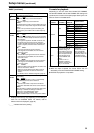
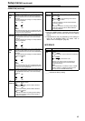
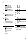
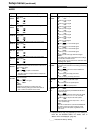
508*
1
BINARY GP
For setting the usage status for the user bits of the
time code generated by the TCG.
0000 000 :
No character set specified
0001 001 :
8-bit character set complying with the ISO646 and
ISO2022 standards
0002 010 :
Undefined
0003 011 :
Undefined
0004 100 :
Undefined
0005 101 :
Page/line
0006 110 :
Undefined
0007 111 :
Undefined
509
PHASE
CORR
For setting whether to control the phase correction of
the LTC output during playback.
0000 OFF :
The phase correction is not controlled.
0001 ON :
The phase correction is controlled.
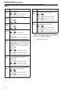
510*
1
TCG CF
FLAG
For selecting whether to set the CF flag of the TCG to
ON.
0000 OFF :
The CF flag is set to OFF.
0001 ON :
The CF flag is set to ON.
No./Item Description of setting
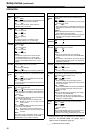
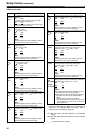
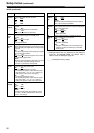
511*
1
DF MODE
For selecting whether to use the DF or NDF mode for
CTL and TCG.
0000 DF :
The drop frame (DF) mode is used.
0001 NDF :
The non-drop frame (NDF) mode is used.
512*
1
TC OUT REF
When the TCG switch of the front panel is set to EXT,
it switches the phase of time code output from the TC
OUT connector for external LTC input. (In EE mode
only)
0000 VOUT :
Match the output image.
0001 TC_IN :
Match the external time code input.
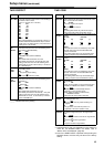
513
VITC OUT
For selecting how to output the VITC signal which is
superimposed onto the output video signal.
0000 SBC :
In the playback mode, the time code recorded in
the SBC area*
A
is output.
0001 VAUX :
In the playback mode, the time code recorded in
the VAUX area*
B
is output.
<Notes>
z The VITC information which is detected by the HD
serial input is automatically recorded in the VAUX
area when the images are recorded.
z When “23/24,” “25(HD),” “25(SD),” “50(HD)” or
“50(SD)” is selected as the menu item No.25
SYSTEM FREQ setting and VAUX is selected as
the VITC OUT setting, the time code which is
output may not be continuous.
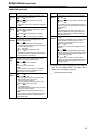
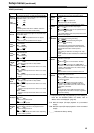
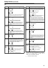
514*
1
HD EMBD
VITC
For selecting whether to superimpose the VITC
information onto the HD serial output.
0000 OFF :
The VITC information is not superimposed.
0001 ON :
The VITC information is superimposed.
515*
1
HD EMBD
LTC
For selecting whether to superimpose the LTC
information onto the HD serial output.
0000 OFF :
The LTC information is not superimposed.
0001 ON :
The LTC information is superimposed.