


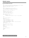

CUE INPUT IMPEDANCE SW
This sets the CUE input impedance.
HIGH/600
™
129
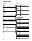
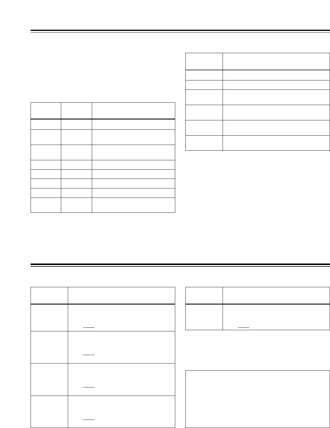
Connector signals
PARALLEL REMOTE (50P)
Refer to 50P IN/OUT ASSIGN on the function menu
(page 75) for the connection pin signals.
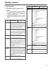
ENCODER REMOTE(15P)
Pin No. Signal
1 FRAME GROUND
4 REM (G)
7 REM RX (X)
REMOTE CONTROL PROTOCOL RECEIVE
8 REM TX (X)
REMOTE CONTROL PROTOCOL TRANSMIT
14 REM RX (Y)
REMOTE CONTROL PROTOCOL RECEIVE
15 REM TX (Y)
REMOTE CONTROL PROTOCOL TRANSMIT
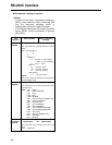
RS-232C
(D-SUB 25-pin, crossover cable supported)
Pin No. Signal Description
1 FG Protective ground (frame ground)
2 RXD Received data (data is sent to PC)
3 TXD Transmitted data (data is received
from PC)
4 CTS Clear to send (shorted with pin 5)
5 RTS Request to send (shorted with pin 4)
6 DTR Data terminal ready (no processing)
7 SG Signal ground
20 DSR Data set ready (+ voltage output after
communication enable status)
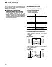
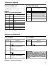
Printed circuit boards
F1 board (ADDA)
Switch No. What is set
SW1
SW101 AUDIO INPUT IMPEDANCE SW
This sets the CH2 audio input impedance.
HIGH/600
™
SW201 AUDIO INPUT IMPEDANCE SW
This sets the CH3 audio input impedance.
HIGH/600
™
SW301 AUDIO INPUT IMPEDANCE SW
This sets the CH4 audio input impedance.
HIGH/600
™
The underlining (__) denotes the factory setting mode.
AUDIO INPUT IMPEDANCE SW
This sets the CH1 audio input impedance.
HIGH/600
™
H3 board (CUE)
Switch No. What is set
SW101
CAUTION:
These servicing instructions are for use by
qualified service personnel only. To reduce the
risk of fire or electric shock do not perform any
servicing other than that contained in the
operating instructions unless you are qualified
to do so.