


95
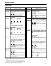
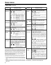
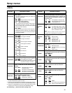
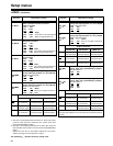
Setup menus
<Note>
Setup menu items No.638, 639, 640, 641 and 642 do not function
when the AJ-UC1700G optional board has not been installed.
The underlining (__) denotes the factory setting mode.
*UP: With HD output (HD tape playback or up-converted output)
*DW: With SD output (SD tape playback or down-converted output)
<VIDEO>
(continued)
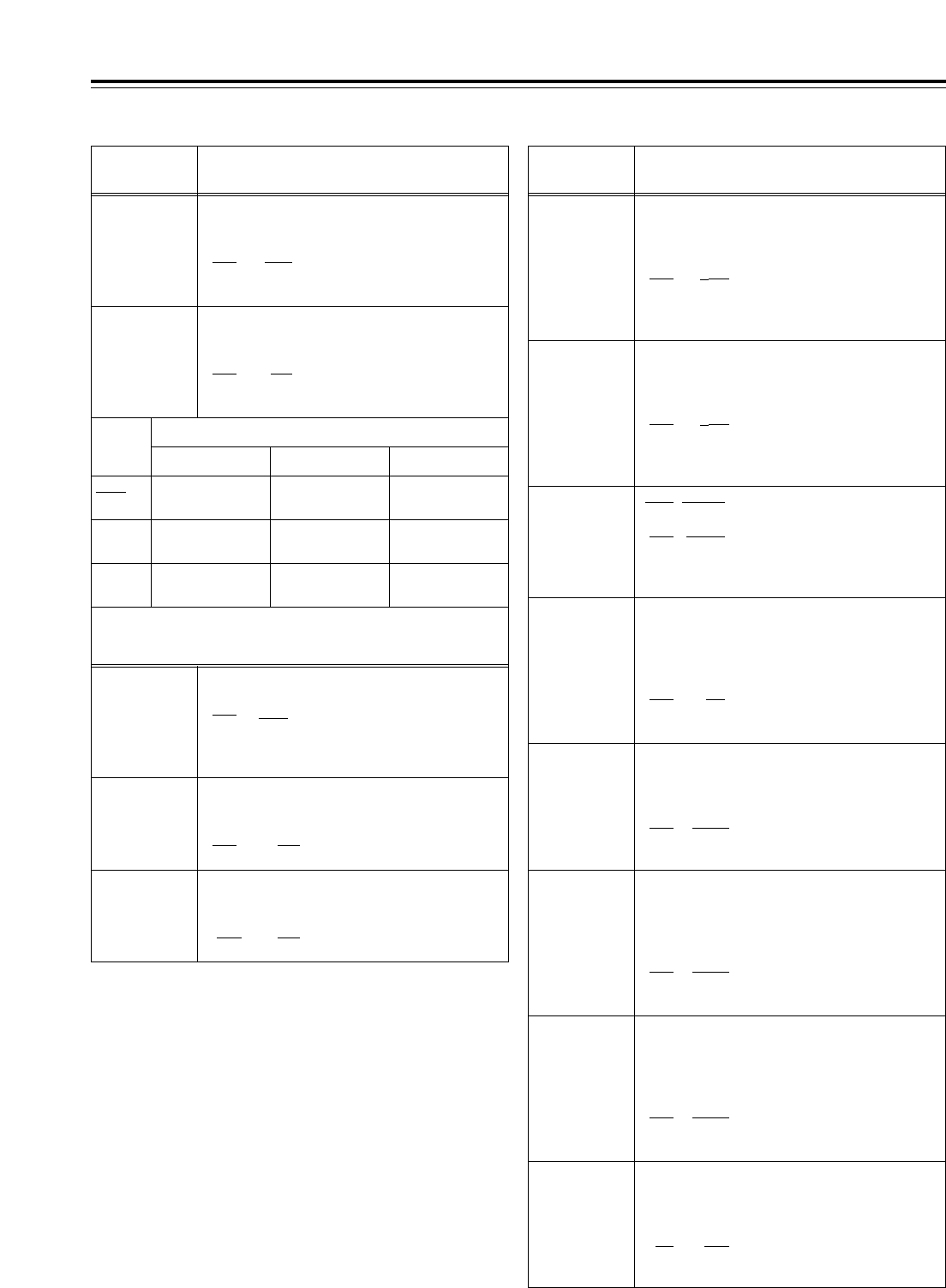
No./Item Description of setting No./Item Description of setting
637*
2
480i
>
SD_
OUT
For selecting the SD output signal format
during 480i tape (DVCPRO50, DVCPRO, DV or
DVCAM) playback. (See table below.)
0000 480i
0001 480i
0002 480p
636*
2
480i
>
HD_
OUT
For selecting the HD output signal format
during 480i tape (DVCPRO50, DVCPRO, DV or
DVCAM) playback. (See table below.)
0000 1080i
0001 720p
0002 ---------
0000 1080i (up-
converted output)
480i
(no conversion)
480i
(no conversion)
720p (up-
converted output)
480i
(no conversion)
480i
(no conversion)
Muted 480p* (up-
converted output)
480i
(no conversion)
0001
0002
HD SDI OUT SD SDI OUT
Output connectors
VIDEO OUT
638*
1
IN U/C
MODE
For selecting the up-conversion picture frame
when SD SDI input signals are supplied.
0000 FIT_V
: Side panel mode
0001 FIT_H:
Top and bottom cut in vertical
direction
0002 FIT_HV
:
Stretch mode
639*
1
I U/C RESP H
For selecting the horizontal frequency band
during the up-conversion of SD SDI input
signals.
0000 STD
0001 NARROW
640*
1
I U/C RESP V
For selecting the vertical frequency band
during the up-conversion of SD SDI input
signals.
0000 STD
0001 NARROW
642*
2
I U/C ENH
V
For accentuating the vertical contours during
up-conversion of SD SDI input signals.
0000 0dB
0001
i
0.7dB
0002
i
1dB
0003
i
1.2dB
0004
i
1.5dB
0005
i
2dB
650
STYLE
0000* CMPNT*
: Level adjustment mode for the
component style
0001 CMPST
: Level adjustment mode for the
composite style
*
The asterisk denotes the factory setting for
AJ-HD1700E.
For adjusting the black level of the HD SDI
output.
50
j
10.0%
::
150
0.0%
::
250
i
10.0%
<Note>
This setting takes effect when
“CMPNT” has been selected as the
setup menu item No.650 setting.
656
BK LVL
(HD)*
UP
655
Pr LVL (HD)*
UP
For adjusting the PB level of the HD SDI
output.
(
j
to
0 dB
to
i
3 dB)
0000 0.0%
::
1000 100.0%
::
1413 141.3%
651*
3
HUE STYLE
(SD)*
DW
For selecting the rotational axis of the chroma
phase adjustment.
0000 Pb-Pr
: The axis rotates in a perfect
circle on the SDI (component
style) vectorscope.
0001
U-V
: The axis rotates in a perfect
circle on the analog (composite
style) vectorscope.
653
Y LVL (HD)*
UP
For adjusting the Y level of the HD SDI output.
(
j
to
0 dB
to
i
3 dB)
0000 0.0%
::
1000
100.0%
::
1413 141.3%
654
Pb LVL
(HD)*
UP
For adjusting the PB level of the HD SDI
output.
(
j
to
0 dB
to
i
3 dB)
0000 0.0%
::
1000 100.0%
::
1413 141.3%
<Note>
This setting takes effect when
“CMPNT” has been selected as the
setup menu item No.650 setting.
<Note>
This setting takes effect when
“CMPNT” has been selected as the
setup menu item No.650 setting.
<Note>
This setting takes effect when
“CMPNT” has been selected as the
setup menu item No.650 setting.
<Note>
The numbers on the superimposed
display are approximations only.
<Note>
During SD tape playback, the VTR cannot be operated in the 60
Hz mode.
*1:This item is not displayed when the 23/24 Hz or 25 Hz (HD or
SD) mode has been selected as the system menu item No.25
(SYSTEM FREQ) setting.
*2: This item is not displayed when the 23/24 Hz, 25 Hz (HD or SD)
or 50 Hz mode has been selected as the system menu item
No.25 (SYSTEM FREQ) setting.
*3:This item is not displayed when the 50 Hz or 25 Hz (HD or SD)
mode has been selected as the system menu item No.25
(SYSTEM FREQ) setting.
* Setup menu item No.107 and INPUT CHECK do not function,
and the same signal as this signal line is output.
641*
2
I U/C ENH
H
For accentuating the horizontal contours
during up-conversion of SD SDI input signals.
0000 0dB
0001
i
0.7dB
0002
i
1dB
0003
i
1.2dB
0004
i
1.5dB
0005
i
2dB
<Note>
The numbers on the superimposed
display are approximations only.