


18
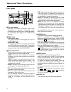
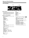
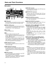
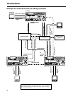
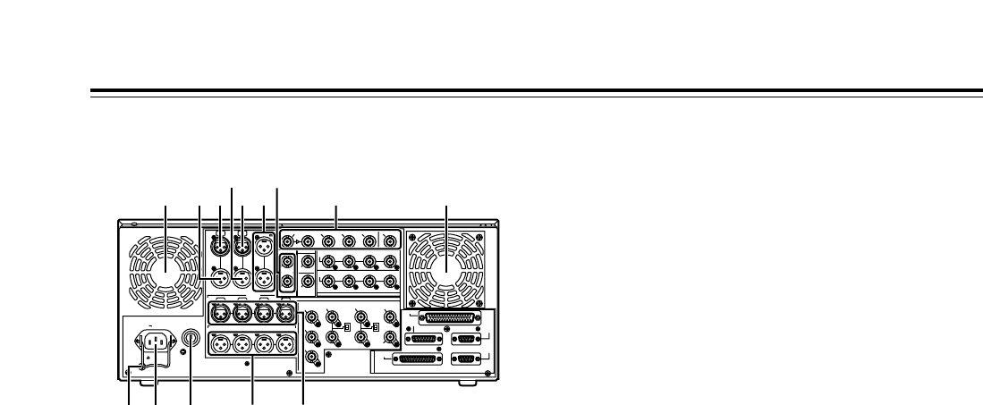
Rear panel
1
AC IN socket
Using the power cord supplied, connect one end to
this socket and the other end to the power outlet.
2
SIGNAL GND terminal
This is connected to the signal ground terminal on
the component connected to this VTR in order to
minimize noise. It is not a safety ground.
3
Fuse holder
A fuse is inserted here.
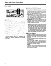
4
Fan
The fan is used to cool down the VTR.
If the fan has been stopped due to some kind of
problem, “
W
” appears on the time code display and
a beeping sound is heard.
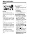
If the VTR is made to continue operating in the
warning status, the temperature inside the deck
rises, and when it exceeds the safety temperature,
all the VTR’s operations will be shut down.
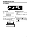
5
TIME CODE IN connector
This connector is used to record an external time
code onto the tape.
6
TIME CODE OUT connector
During playback, the playback time code is output
through this connector. During recording, the time
code generated by the internal time code generator
is output.
7
CUE IN connector
The analog signals to be recorded on the CUE
tracks are input through this connector.
Audio signals from a microphone can also be
recorded by selecting the
j
60 dB input mode for
setup menu item No.704 (CUE IN LV).
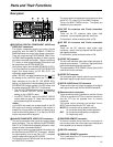
Parts and Their Functions
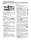
8
CUE OUT connector
The analog signals recorded on the CUE tracks are
output through this connector.
9
MONITOR OUT connectors
The CH1, CH2, CH3, CH4, CH5, CH6, CH7 and
CH8 PCM audio signals or CUE signals are output
through these connectors.
:
ANALOG AUDIO IN connectors
These are the analog audio input connectors (for
CH1, CH2, CH3 and CH4).
;
ANALOG AUDIO OUT connectors
The analog audio signals (CH1, CH2, CH3 and
CH4) are output through these connectors.
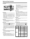
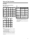
<
HD SERIAL DIGITAL COMPONENT AUDIO/VIDEO
IN/OUT connector/ACTIVE THRU
The HD digital component audio and video signals
complying with the SMPTE 292M and 299M
standards are input and output through this
connector.
Signals with the time code, menu or other
superimposed information are output from the HD
SDI MONITOR.
For INPUT CHECK, refer to the INPUT CHECK
output table on page 15.
=
SDTI IN and OUT connectors (SDTI, optional
accessory)*
1
, SD SDI IN/ACTIVE THRU (SD up-
converter, optional accessory)*
2
*1: These connectors handle compressed data
input and output signals complying with the
SMPTE 305M and 321M standards.
*2: These input connectors enable SD SDI signals
complying with the SMPTE 259M-C standard to
be up-converted to HD signals and recorded.
<Notes>
• The optional AJ-UC1700G SD serial digital input
board and optional AJ-YAC150P SDTI input
board cannot be installed at the same time.
Install one or the other.
• SDTI does not function when the 25 Hz (HD or
SD) or 50 Hz mode has been selected as the
system menu item No.25 (SYSTEM FREQ)
setting.
PUSHPUSH
PUSH PUSH PUSH PUSH
SIGN
AC IN
TC
IN IN L
OUT
CH 1
AUDIO IN
CH 2 CH 3 CH 4
VIDEO OUT
(WFM)
ON
OFF
75≠
ON
OFF
75≠
(SUPER)
1
2
3
SD REF IN
CH1·2
AUDIO
OUT
CH3·4 CH5·6 CH7·8
HD REF IN HD REF OUT
SD
REF OUT
RS-232C
ENCODER
REMOTE
REMOTE
IN/OUT
REMOTE
OUT
PARALLEL
CH 1 CH 2 CH 3 CH 4
OUT R
CUE MON
PUSH PUSH PUSH
L
GD
CH1·2
AUDIO
IN
CH3·4 CH5·6 CH7·8
ACTIVE
THROUGH
(SUPER)
ANALOG
DIGITAL AUDIO
SD SDI
(OPTION)
HD SDI
SDTI
R
E
M
O
T
E
IN
OUT
OUT 1IN OUT 2 OUT 3
MONITOR (SUPER)
MONITOR
AUDIO OUT
4 45
8
76
12 3
9 <
:;
=