


91
Setup menus
The underlining (__) denotes the factory setting mode.
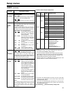
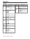
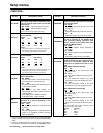
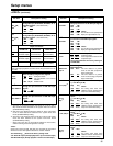
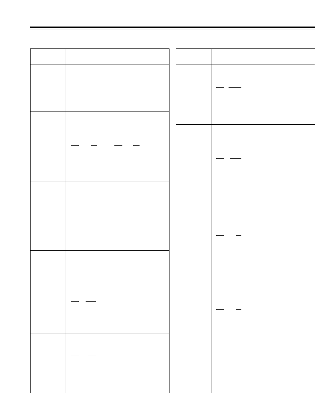
<TIME CODE>
No./Item Description of setting
500*
4
VITC BLANK
For selecting whether or not to output the
VITC signal at the positions selected by setup
menu items No.501 (VITC POS-1) and No.502
(VITC POS-2).
0000 BLANK
: The VITC signal is not output.
0001 THRU
: The VITC signal is output.
<Note>
Only the SD output takes effect at this setting.
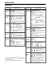
501*
4
VITC POS-1
For setting the position where the VITC signal
is to be inserted.
<59/60Hz> <50Hz, 25Hz (SD)>
0000 10L 0000 7L
:: ::
0006 16L 0004 11L
:: ::
0010 20L 0015 22L
<Notes>
• The same line as the one selected by the setup menu
item No.502 (VITC POS-2) cannot be selected.
• Only the SD output takes effect at this setting.
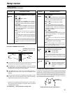
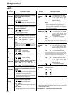
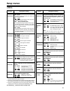
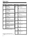
505*
1
TCG REGEN
For selecting the regeneration signal when
REGEN has been selected as the TCG (time
code generator) mode.
0000 TC&UB
:
Regeneration applies to both the time code
and user’s bit.
0001 TC
:
Regeneration applies only to the time code only.
0002 UB
:
Regeneration applies only to the user’s bit only.
506*
1
REGEN MODE
For selecting the editing mode range when
the VTR is operating in the REGEN mode
while performing editing operations with
“AUTO” selected as the setup menu item
No.503 (TCG MODE) setting.
0000 AS&IN
:
Regeneration applies during assemble or
insert editing.
0001 ASSEM
:
Regeneration applies during assemble editing.
0002 INSRT
:
Regeneration applies during insert editing.
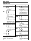
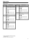
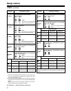
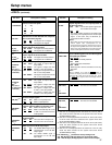
507*
1
TC SOURCE
For selecting the time code to be used when
HD SDI or SD SDI has been selected as the
setup menu item No.600 (VIDEO IN SEL)
setting when an external time code is to be
used.
[When HD SDI has been selected]
0000
INT
:
The time code of the internal time code
generator is used.
0001 EXT_L
:
LTC of the TIME CODE IN connector is used.
0002 SLTC
:
The LTC information added to the serial
signals which are input to HD SDI IN is used.
0003 SVITC
:
The VITC information added to the serial
signals which are input to HD SDI IN is used.
[When SD SDI has been selected]
0000 INT
:
The time code of the internal time code
generator is used.
0001 EXT_L
:
LTC of the TIME CODE IN connector is used.
0002 VITC
:
The VITC information added to the serial
signals which are input to SD SDI IN is used.
<Note>
If the VIDEO IN SEL input selection is changed, the time
code is converted as shown below.
[HD_SDI] [SD_SDI]
INT
↔
INT
EXT_L
↔
EXT_L
SLTC
↔
EXT_L
SVITC
↔
VITC
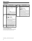
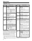
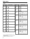
502*
4
VITC POS-2
For setting the position where the VITC signal
is to be inserted.
<59/60Hz> <50Hz, 25Hz (SD)>
0000 10L 0000 7L
:: ::
0008 18L 0006 13L
:: ::
0010 20L 0015 22L
<Notes>
• The same line as the one selected by the setup menu
item No.501 (VITC POS-1) cannot be selected.
• Only the SD output takes effect at this setting.
503*
1
TCG MODE
For setting the synchronization of the internal
time code generator.
0000 REGEN
:
The time code reader is synchronized with the
time code which is read from the tape.
0001 PRE
:
Presetting is enabled at the operation panel or
by the remote controller.
0002 AUTO
:
The REGEN and PRE settings are
automatically switched in accordance with the
operation mode.
In the editing mode: REGEN is selected.
In all other modes: PRE is selected.
504*
1
RUN MODE
For setting when the internal time code
generator is to advance depending on the
operation mode.
0000 REC
:
The time code generator is advanced during
recording.
0001 FREE
:
The time code generator is advanced while the
power is on regardless of which operation
mode is established.
No./Item Description of setting
*1: This item is not displayed when the 23/24 Hz or 25 Hz (HD or SD) mode
has been selected as the system menu item No.25 (SYSTEM FREQ)
setting.
*2: This item is not displayed when the 23/24 Hz or 25 Hz (HD) mode has
been selected as the system menu item No.25 (SYSTEM FREQ) setting.