


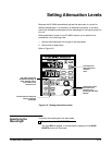

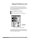

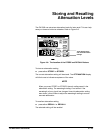


Setting the Reference Level
User Reference
2 --- 12
The reference mode has two primary applications:
1. Reading total attenuation (insertion loss)
2. Approximating signal p ower
The total attenuation of any attenuator is the sum of the attenuation caused
by the connections (the insertion loss) and the attenuation caused by the
active element. Since the insertion loss is dependent on many factors, it is
hard to determine this value precisely. Some of the factors that affect inser-
tion loss are the condition of the connectors, the cleanliness of the connec-
tors, and the mode pattern of the fiber. Nonetheless, you can measure
insertion loss.
Step 1: Connect a stable source to an optical power meter using two
optical cables that have been joined with an in-line adapter.
Step 2: Measure the power on a suitable optical power meter and
measure the optical power in dBm.
Step 3: Disconnect the cables at the in-line adapter and connect them
to the optical attenuator (which should be set at minimum attenuation).
Step 4: Measure the resultant power in dBm.
The insertion loss (within the connector uncertainty) is the difference be-
tween the power reading with only the optical cables and the reading with
the cables plus the attenuator. The insertion loss specification for the
OA 5000 attenuators is ≤2.0 dB. The total attenuation is the insertion loss
plus the attenuation level shown on the OA 5000. Thus, by setting the refer-
ence level to the value of the insertion loss and enabling the reference
display mode, the OA 5000 can display the total attenuation of the attenua-
tion system.
Measuring Insertion
Loss