


DUA1800-0AAA04
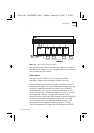
The LinkBuilder MSH 1-3
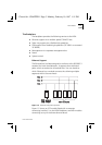
1
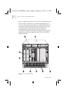
MSH Chassis
- The 11-slot chassis that holds the backplane into
which all components are installed. See
The Chassis
on page 1-4
2
Display Panel
- Can be fitted front or back. Provides your local
interface to the control and management of the MSH. See
The
Display Panel
on page 1-9
.
3
Power Supply Units
- Distributes power to the other modules.
One unit is essential for operation, two are recommended for
resilience. See
Power Supply Units (PSU)
on page 1-8
.
4
Power Inlet Panel
- Provides the power connection via two IEC
sockets. See
The Power Supply Unit And Power Inlet Panel
on
page 2-8
.
5
Thermal Management Unit
- A fan unit that supplies cooling
air to the modules. See
The Thermal Management Unit (TMU)
on
page 1-10
.
6
Locking Bar
- This must be fitted to prevent removal of modules
and power supply units by unqualified personnel. See
The Locking
Bar
on page 2-5
.
7
Documentation Holder
- A useful place to store module user
guides. See
Storing The User Guides
on page 2-24
.
8
Module Slot and Blanking Plate
- There are eleven identical
slots that can take one of a range of modules. Blanking plates
that cover 1, 3 and 5 vacant slots are supplied.
See Choosing Slots
For Modules
on page 3-17
and Blanking Plates
on page 3-16
.
9
Module
- One of a wide range available from 3Com. See
The
Modules
on page 1-8.
Packaged with the MSH chassis, but not shown on Figure 1-1:
The Rack Mounting Kit
- Consists of a pair of brackets that
allow the MSH to be mounted into a 19 inch rack. See
Installation
Into A 19 Inch Rack
on page 2-4
.
Chassis.bk : CHAPTER1 Page 3 Monday, February 10, 1997 1:11 PM