


DUA1800-0AAA04
The Thermal Management Unit 2-21
connections. When fitted, the cable support tray also provides the
correct clearance between chassis mounted one above the other.
If you decide to use the tray, the user guide holder that is located
underneath the chassis (see
Storing The User Guides
on page
2-24) must be moved as in this position the user guides will be
inaccessible.
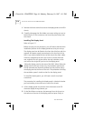
To move the user guide holder:
1
Remove the user guide holder by loosening the four screws that
secure it in position underneath the chassis.
2
With the cable support tray upside down, slide the user guide
holder through the slot at the front of the tray until the four
screw holes align. Locate the four screws and tighten.
To fit the cable support tray:
1
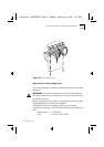
Place the cable support tray onto a flat surface. Sit the MSH
chassis on the tray so that two screw holes on either side of the
tray match up with those on the chassis body.
2
Insert the four screws and tighten.
Fixing the cables:
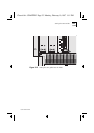
The cable support tray can contain up to twelve adjustable cable
clips. Once you have fitted the tray, module cables can be secured
in two ways:
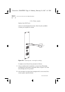
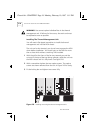
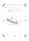
1
Figure 2-10: Let cables drop down the front of the chassis, insert
them through the front of the cable clip and route them out
through the back of the cable support tray. Tighten the cable clip.
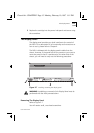
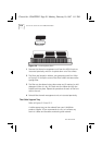
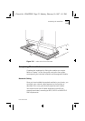
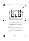
2
Figure 2-11: The bracket that holds the cable clips can slide away
from the MSH chassis; undo the two thumb-screws, slide the
bracket out and retighten the thumb-screws. Let cables drop
down the front of the chassis, insert them through the back of
Chassis.bk : CHAPTER2 Page 21 Monday, February 10, 1997 1:11 PM