


DUA1800-0AAA04
The Thermal Management Unit 2-17
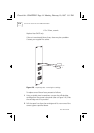
ensure that the connection is good. The connector is keyed, so if
necessary turn it around to make it fit the socket.
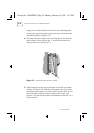
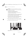
3
Locate the display panel into position at the top of the chassis.
Secure using the three screws provided.
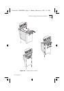
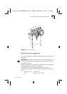
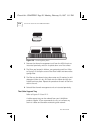
The Thermal Management Unit
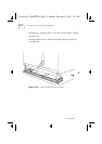
The thermal management unit fits into the bottom of the MSH
chassis, underneath the module slots. It consists of an open-top
tray containing axial fans that draw in cooling air through a grill at
the front of the tray. The air circulates through the chassis and is
expelled through ventilation holes which must be kept free of
obstruction at all times.
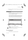
The thermal management unit can be installed or replaced whilst
the MSH is powered up without any detrimental effect to its
operation. You should install or replace the TMU with minimal
delay when the MSH is powered up: serious damage can be
caused through overheating if the MSH is allowed to operate
without a TMU installed.
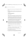
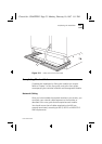
On the underside of the unit, each fan is covered with a filter to
prevent dust from entering into the chassis. These filters should
be removed and inspected regularly and cleaned when necessary.
See
Cleaning The Filters
on page 2-19
.
The MSH is delivered with the thermal management unit
installed. However, in the unlikely event of a fan failure, you will
need to remove the unit and return it to your supplier. The
thermal management unit takes power from the MSH backplane.
This backplane connection also provides a detection service; an
LED located on the display panel will notify you immediately if a
fan has failed. If a Management Module has been fitted, a signal
will be sent to the module, which will in turn send an event to the
remote Network Manager.
Chassis.bk : CHAPTER2 Page 17 Monday, February 10, 1997 1:11 PM