


DUA1800-0AAA04
The Display Panel 1-9
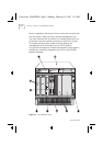
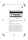
Power is supplied to the chassis via two IEC sockets (the top
socket serves the left-hand PSU) on a fixed power inlet panel
fitted in the chassis between the right-hand PSU slot (PSU 2), and
the module slots. The two sockets provide resilience against
power supply cable or fuse faults.
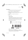
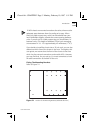
The Display Panel
The display panel provides the following features:
■
Lamps Button
The Lamps button allows you to carry out an LED test which
shows you that all the LEDs on the display panel and on modules
installed into the chassis, are working. If an LED on the display
panel does not light, refer to Chapter 5 of this user guide; if it is a
problem with a module LED, refer to the user guide that
accompanies the product.
■
Reset Button
Pressing the Reset button restarts the MSH. To prevent an
accidental reset of the modules, the Enter button on the
four-button keypad must be pressed at the same time as the
Reset button
.You should only need to reset the MSH immediately after
installation. It is advisable not to use the Reset button during
normal operation, as this could cause loss of data.
■
RS232 Port
This is a 25-way D-Type connector to which you may connect a
local management terminal directly or via a modem. Note that, in
order to use this port, a LinkBuilder MSH Management Module
must be installed into the chassis.
The display panel also gives you simple fault finding with a line of
comprehensive LEDs, which are explained in Chapters 4 and 5.
Chassis.bk : CHAPTER1 Page 9 Monday, February 10, 1997 1:11 PM