


DUA1800-0AAA04
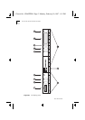
The Display Panel 4-3
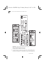
1 RS232 Port
- Used for out-of-band management. See
The RS232
Serial Port
on page 4-7
.
2 Reset Button
- Used with the Enter button, resets the MSH
chassis to default configuration. See
Resetting The LinkBuilder
MSH
on page 4-6
.
3 Lamps Button
- Tests LED operation. See
Testing LEDs
on page
4-5
.
4Power LED -
Signifies state of power to chassis. See
The LEDs
on
page 4-4
.
5 Select Button
- Used in conjunction with the LCD display. See
The Four-button Keypad
on page 4-6
.
6 Next Button
- Used in conjunction with the LCD display. See
The
Four-button Keypad
on page 4-6
.
7 Previous Button
- Used in conjunction with the LCD display. See
The Four-button Keypad
on page 4-6
.
8 LCD Display
- Used in conjunction with 5, 6, 7 and 9 for
displaying information about your MSH setup. See
The
Four-button Keypad
on page 4-6
.
9 Enter Button
- Used in conjunction with the LCD display, and
with the Reset button to reset the MSH chassis to default
configuration. See
The Four-button Keypad
on page 4-6
.
10 Power Fail LED
- Indicates power supply unit failure. See
The
LEDs
on page 4-4
.
11 Fan Fail LED
- Indicates failure of one or more fans in the thermal
management unit. See
The LEDs
on page 4-4
.
12 Module LEDs
- Indicate state of modules installed in the chassis.
See
The LEDs
on page 4-4
.
Chassis.bk : CHAPTER4 Page 3 Monday, February 10, 1997 1:11 PM