


2-12 C
HAPTER
2: I
NSTALLING
T
HE
L
INK
B
UILDER
MSH
DUA1800-0AAA04
6
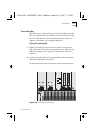
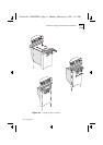
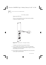
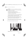
Simultaneously, press the ejector flaps firmly down into the closed
position. See Figure 2-4. Check that the module has been
properly seated by placing both your thumbs on the front panel
and firmly pushing the module home. Check that the module
front panel is flush with the chassis and surrounding modules.
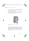
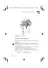
7
Using a suitable screwdriver, tighten the single security screw that
is at the foot of each PSU, adjacent to the ejector. This captive
screw is shown removed from the unit in Figure 2-3 for clarity.
8
Reposition locking bar and fully tighten the two screws to secure
it in place.
9
Once you have completed the installation of all components into
the chassis, you can power the MSH up and verify that it is
operating correctly. See
Completing The Installation
on page
2-23.
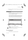
Removing The Power Supply Unit
Remove the power cord corresponding to the PSU you intend to
remove. The top socket feeds the left-hand PSU; the bottom one
the right-hand PSU. Remove the locking bar from the front of the
chassis. Loosen the security screw at the foot of the PSU. To
unlock the PSU ejector, press on the sprung catch and move the
flaps to the open position. This operation must be applied
simultaneously to both ejectors on the PSU
Removing one of the two power supply units from an operational
MSH will not cause any damage to your equipment. However,
packets of data passing through the unit at the time of removal
can be corrupted. Most network protocols will transparently
recover if this happens.
Before you power down the chassis make sure you inform
affected users or the Network Manager. The effect on end users
of powering down the MSH is varied. It is up to the Network
Manager to decide how best to deal with the situation.
Chassis.bk : CHAPTER2 Page 12 Monday, February 10, 1997 1:11 PM