


5 - Programming the DC Source
46
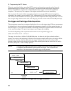
Measurement Trigger Model
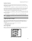
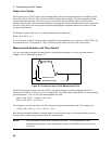
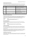
Figure 5-3 is a model of the measurement trigger system. The rectangular boxes represent states. The
arrows show the transitions between states. These are labeled with the input or event that causes the
transition to occur.
DATA ACQUIRED
INITIATED STATE
IDLE STATE
ABOR
*RST
TRIGGER RECEIVED
INITiate:NAME ACQ
IS AN OUTPUT
CHANGE IN
PROGRESS?
SETTLING DELAY
YES
NO
Figure 5-3. Model of Measurement Trigger System
Enabling the Measurement Trigger System
When the dc source is turned on, the trigger system is in the idle state. In this state, the trigger system is
disabled and it ignores all triggers. Sending the following commands at any time returns the trigger
system to the idle state:
ABORt
*RST
The INITiate commands move the trigger system from the idle state to the initiated state. This enables
the measurement system to receive triggers. To initiate the measurement trigger system, use:
INIT:NAME ACQ
After a trigger is received and the data acquisition completes, the trigger system will return to the idle
state. Thus it will be necessary to initiate the system each time a triggered measurement is desired.
Selecting the Measurement Trigger Source
The trigger system is waiting for a trigger signal in the initiated state. Before you generate a trigger, you
must select a trigger source. The following measurement trigger sources can be selected:
BUS -
Selects GPIB bus triggers.
EXTernal -
Selects the external trigger input as the trigger source.