


Programming the DC Source - 5
51
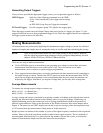
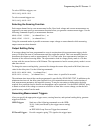
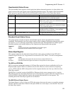
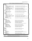
Questionable Status Group
The Questionable Status registers record signals that indicate abnormal operation. As shown below, the
group consists of the same register types as the Status Operation group. The outputs of the Questionable
Status group are logically-ORed into the QUEStionable summary bit (3) of the Status Byte register.
Register Command Description
Condition STAT:QUES:COND? (@<channel list>) A register that holds real-time status of the circuits
being monitored. It is a read-only register.
PTR Filter STAT:QUES:PTR <n> (@<channel list>) A positive transition filter that functions as described
under
STAT:QUES:NTR|PTR commands in chapter
6. It is a read/write register.
NTR Filter STAT:QUES:NTR <n> (@<channel list>) A negative transition filter that functions as described
under
STAT:QUES:NTR|PTR commands in chapter
6. It is a read/write register.
Event STAT:QUES:EVEN? (@<channel list>) A register that latches any condition that is passed
through the PTR or NTR filters. It is a read-only
register that is cleared when read.
Enable STAT:QUES:ENAB <n> (@<channel list>) A register that functions as a mask for enabling specific
bits from the Event register. It is a read/write register..
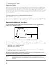
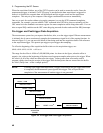
Standard Event Status Group
This group consists of an Event register and an Enable register that are programmed by Common
commands. The Standard Event event register latches events relating to instrument communication status
(see figure 5-5). It is a read-only register that is cleared when read. The Standard Event enable register
functions similarly to the enable registers of the Operation and Questionable status groups.
Command Action
*ESE
programs specific bits in the Standard Event enable register.
*ESR?
reads and clears the Standard Event event register.
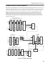
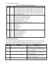
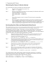
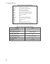
Status Byte Register
This register summarizes the information from all other status groups as defined in the IEEE 488.2
Standard Digital Interface for Programmable Instrumentation. See Table 5-1 for the bit configuration.
Command Action
*STB? reads the data in the register but does not clear it (returns MSS in bit 6)
serial poll clears RQS inside the register and returns it in bit position 6 of the response.
The MSS and RQS Bits
MSS is a real-time (unlatched) summary of all Status Byte register bits that are enabled by the Service
Request Enable register. MSS is set whenever the dc source has one or more reasons for requesting
service. *STB? reads the MSS in bit position 6 of the response but does not clear any of the bits in the
Status Byte register.
The RQS bit is a latched version of the MSS bit. Whenever the dc source requests service, it sets the
SRQ interrupt line true and latches RQS into bit 6 of the Status Byte register. When the controller does a
serial poll, RQS is cleared inside the register and returned in bit position 6 of the response. The
remaining bits of the Status Byte register are not disturbed.
The MAV Bit and Output Queue
The Output Queue is a first-in, first-out (FIFO) data register that stores dc source-to-controller messages
until the controller reads them. Whenever the queue holds one or more bytes, it sets the MAV bit (4) of
the Status Byte register.