


5 - Programming the DC Source
50
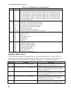
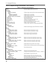
Table 5-1. Bit Configurations of Status Registers
Bit Signal Meaning
0
1
2
3
4
5
6
CV
CL+
CL-
CC
VL+
VL-
OFF
Operation Status Group
The selected output is in constant voltage mode (applies only in voltage priority mode)
The selected output is in positive current limit (applies only in voltage priority mode)
The selected output is in negative current limit (applies only in voltage priority mode)
The selected output is in constant current mode (applies only in current priority mode)
The selected output is in positive voltage limit (applies only in current priority mode)
The selected output is in negative voltage limit (applies only in current priority mode)
The selected output is OFF
0
1
2
4
10
12
14
OV+
OV-
PCLR
OT
UNR
OSC
MeasOvld
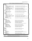
Questionable Status Group
The positive overvoltage protection has tripped
The negative overvoltage protection has tripped
No communication with the selected output
The overtemperature protection has tripped
The output is unregulated
The oscillation protection has tripped
Output measurement exceeded capability of the range
0
2
3
4
5
7
OPC
QYE
DDE
EXE
CME
PON
Standard Event Status Group
Operation complete
Query error
Device-dependent error
Execution error
Command error
Power-on
2
3
4
5
6
7
WTG
QUES
MAV
ESB
MSS
RQS
OPER
Status Byte and Service Request Enable Registers
The unit is waiting for a trigger
Questionable status summary bit
Message Available summary bit
Event Status Summary bit
Master Status Summary bit
Request Service bit
Operation status summary bit
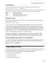
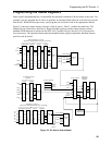
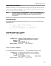
Operation Status Group
The Operation Status registers record signals that occur during normal operation. As shown below, the
group consists of a Condition, PTR/NTR, Event, and Enable register. The outputs of the Operation Status
register group are logically-ORed into the OPERation summary bit (7) of the Status Byte register.
Register Command Description
Condition STAT:OPER:COND? (@<channel list>) A register that holds real-time status of the circuits
being monitored. It is a read-only register.
PTR Filter STAT:OPER:PTR <n> (@<channel list>) A positive transition filter that functions as described
under STAT:OPER:NTR|PTR commands in chapter 6.
It is a read/write register.
NTR Filter STAT:OPER:NTR <n> (@<channel list>) A negative transition filter that functions as described
under STAT:OPER:NTR|PTR commands in chapter 6.
It is a read/write register.
Event STAT:OPER:EVEN? (@<channel list>) A register that latches any condition that is passed
through the PTR or NTR filters. It is a read-only
register that is cleared when read.
Enable STAT:OPER:ENAB <n> (@<channel list>) A register that functions as a mask for enabling specific
bits from the Event register. It is a read/write register.