


B - Performance and Calibration Procedures
96
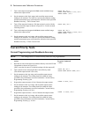
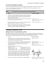
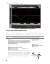
Figure B-2. Transient Waveform Voltage Priority
Current Priority Transient Recovery Time
This test measures the time for the output current to recover to within the specified value following a
±1V change in the output voltage. The test setup uses a 0.47
µF capacitor across the output of the
generator to form an approximate 25
µs time constant with the 50 ohm output of the function generator.
NOTE: Turn off the output of the dc source before connecting the function generator.
Action Program Commands
1. Turn off the dc source and connect the output as in Figure B-1f with
the function generator across the HI and LO terminals. Remember to
connect the capacitor (0.47
µF) close to the function generator. Keep
all leads as short as possible.
“OUTP OFF,(@1)”
2. Turn on the dc source and program the Current Priority mode.
Program the current to zero amps.
“OUTP ON,(@1)”
“SOUR:FUNC:MODE CURR,(@1)”
“CURR 0,(@1)”
3.
Program the Function Generator as follows:
Frequency = 400Hz to 1kHz Duty cycle = 50%
Wave shape =
±1V square wave.
Set the Tektronics current probe to measure current at 2mA/div.
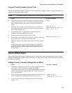
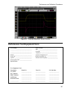
4. Adjust the oscilloscope for a waveform similar to that in Figure B.
The output current should return to within
±1mA in less than 90µs.
Check both loading and unloading transients by triggering on the
positive and negative slope. Record the voltage at time “t” in the
performance test record card under Current Priority Transient
Response Current.
tttt
t
v
Loading
Transient
Unloading
Transient
v
t