


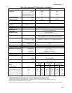

Performance and Calibration Procedures
89
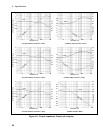
Load Effect Tests
The following tests verify the dc regulation of the output voltage and current. To insure that the values
read are truly dc and not affected by output ripple, several dc measurements should be made and the
average of these readings calculated. An example of how to do this is given below using an Agilent
3458A System Voltmeter programmed from the front panel. Set up the voltmeter and execute the
"Average Reading" program follows:
a. Program 10 power line cycles per sample by pressing NPLC 1 0 ENTER .
b. Program 100 samples per trigger by pressing (N Rdgs/Trig) 1 0 0 ENTER .
c. Set up voltmeter to take measurements in the statistical mode as follows:
Press Shift key, f0, Shift key, N
Press ^ (up arrow) until MATH function is selected, then press >.
Press ^ (up arrow until STAT function is selected then press (ENTER).
d. Set up voltmeter to read the average of the measurements as follows:
Press Shift key, f1, Shift key, N.
Press down arrow until RMATH function is selected, then press >.
Press ^ (up arrow) until MEAN function is selected, then press ENTER.
e. Execute the program by pressing f0, ENTER, TRIG, ENTER
f. Wait for 100 readings and then read the average measurement by pressing f1, ENTER.
To repeat the measurement, perform steps (e) and (f).
Voltage Priority, Constant Voltage Load Effect
This test measures the change in output voltage resulting from a change in output current from about zero
amps to about 0.5 amps.
Action Program Commands
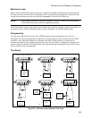
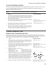
1. Turn off the dc source and connect the output as shown in Figure B-1b
with the DMM across the HI and LO sense terminals. Connect the 20
ohm load resistor and switch across the HI and LO output terminals.
“*RST”
2. Start with the load disconnected (switch open). Turn on the dc source,
program the output voltage to the full-scale value (10.0V), and the
current limit to the maximum value (0.5125A).
“OUTP ON,(@1)”
“VOLT 10,(@1)”
“CURR:LIM 0.5125,(@1)”
3. Set the DVM to the 10V range, and record the output voltage reading.
(zero-load value)
4. Connect the 20 ohm load resistor across the output (close the switch).
Keep the DVM connected.
6.
Read back the N3280A status to be sure that it’s in the
CV mode. This
query should return a Bit value of “
1” for CV mode.
If it is not in CV mode, use a slightly higher value resistor so that the
output current drops slightly.
“STAT:OPER:COND? (@1)”
7. Record the output voltage reading on the DVM. (full-load value)
The difference between these two DVM readings is the Load Effect
voltage and should be within the limits listed in the performance test
record card under Voltage Priority Load Effect Voltage.