


Performance and Calibration Procedures
99
Performing the Calibration Procedure
You can only calibrate the dc source by using SCPI commands within your controller programming
statements. The SCPI calibration commands are explained in chapter 8. Calibration error messages that
can occur during GPIB calibration are shown in table B-3.
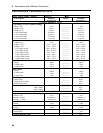
Table B-1 lists the equipment required for calibration. Figure B-1 shows the test setup. Calibrating the
N3280A power supply requires an HP 3458 DMM or something with equivalent voltage and current
measurement accuracy. For all calibration steps, connect the high sense terminal to the high output, and
the low sense terminal to the low output. A general outline of the calibration procedure is as follows:
1. Enable calibration by sending the CAL:STATE ON <password> command. The password argument
is a number which is set at the factory to the model number of the power supply, and can be changed
by the user.
2. Calibrate one or more subsystems using the commands given in the following sections. Calibrate
only one of the 4 output channels at a time. The calibration commands accept only a single channel
number for the channel list arguments.
3. Whenever a subsystem's calibration is changed, all subsystems listed below it must also be re-
calibrated. However, voltage and current subsystems are independent (changing the calibration of
one does not require re-calibration of the other).
4. As each subsystem's procedure is completed, the instrument calculates new calibration constants and
begins using them. These constants are not saved in nonvolatile memory until the CAL:SAVE
command is given. CAL:SAVE can be given after each subsystem is done or given once after all
subsystems are done.
5. Disable calibration by sending CAL:STATE OFF. Any subsystems that were calibrated with a
subsequent CAL:SAVE revert to their previous calibration constants. Note that *RST also sets the
calibration state to OFF.
Enable Calibration Mode
Action Program Commands
1. Reset the unit.
“*RST”
2. Enable calibration mode. (lf the password is incorrect, an error occurs.)
“CAL:STAT ON, 0”
Voltage Priority Mode Programming and Measurement Calibration
Action Program Commands
1. Jumper the High sense terminal to the High output terminal.
Jumper the Low sense terminal to the Low output terminal.
Connect the voltage input of the 3458A multimeter directly to output 1.
2. Select voltage calibration for output 1.
“CAL:VOLT (@1)”
3. Select the first calibration point. *OPC? prevents processing of all
subsequent commands to ensure that the output is stable.
“CAL:LEV P1;*OPC?”
4. Set the 3458A multimeter to the 10V range, measure the output
voltage, and enter the data into the dc source.
“CAL:DATA <value>”
5. Select the second calibration point. *OPC? prevents processing of all
subsequent commands to ensure that the output is stable.
“CAL:LEV P2;*OPC?”
6. Measure the output voltage and enter the data into the dc source.
“CAL:DATA <value>”