


B - Performance and Calibration Procedures
90
Voltage Priority, +Current Limit Load Effect
This test measures the change in output current resulting from a change in output voltage from about zero
volts to about 10 volts.
Action Program Commands
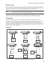
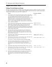
1. Turn off the dc source and connect the output as shown in Figure B-1c
with an ammeter in series with a 20 ohm load resistor across the Hi and
Lo output terminals. Also connect a shorting switch across the resistor.
“*RST”
2. Start with a short across the output (switch closed). Turn on the dc
source and program the output voltage to the maximum positive value
(+10.25V), and the current limit to 0.5A.
“OUTP ON,(@1)”
“VOLT 10.25,(@1)”
“CURR:LIM 0.5,(@1)”
3. Set the ammeter to the 1A range, and record the output current reading
on the ammeter. (shorted-output value)
4. Remove the short (open the switch) from the output of the dc source.
5.
Read back the N3280A status to be sure that it’s in the +
CL mode.
This query should return a Bit value of “
2” for +CL mode.
If it is not in +CL mode, decrease the current limit setting slightly. If
you adjusted the current limit, close the switch and go back to step 3.
“STAT:OPER:COND? (@1)”
6. Record the output current reading on the ammeter. (full-load current
value)
The difference between the two current readings is the Load effect
current and should be within the limits listed in the performance test
record card under Voltage Priority Source Effect +Current.
Voltage Priority, -Current Limit Load Effect Test
This test measures the change in output current resulting from a change in output voltage from about zero
volts to about −10 volts.
Action Program Commands
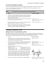
1. Turn off the dc source and connect the output as shown in Figure B-1c
with an ammeter in series with a 20 ohm load resistor across the Hi and
Lo output terminals. Also connect a shorting switch across the resistor.
“*RST”
2. Start with a short across the output (switch closed). Turn on the dc
source and program the output voltage to the maximum negative value
(–10.25V), and the current limit to 0.5A.
“OUTP ON,(@1)”
“VOLT –10.25,(@1)”
“CURR:LIM 0.5,(@1)”
3. Set the ammeter to the 1A range, and record the output current reading
on the ammeter. (shorted-output value)
4. Remove the short (open the switch) from the output of the dc source.
5.
Read back the N3280A status to be sure that it’s in the –
CL mode. This
query should return a Bit value of “
4” for –CL mode.
If it is not in –CL mode, decrease the current limit setting slightly. If
you adjusted the current limit, close the switch and go back to step 3.
“STAT:OPER:COND? (@1)”
6. Record the output current reading on the ammeter. (full-load current
value)
The difference between the two current readings is the Load effect
current and should be within the limits listed in the performance test
record card under Voltage Priority Source Effect –Current.