


Chapter 3 Configuring the System
96
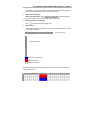
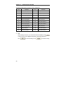
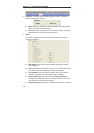
The following table shows NV 7000 I/O card pin assignments.
Pin # Definition Pin # Definition
1 Sensor 1 input signal 11 Relay Normal Close 1
2 Sensor 1 output signal 12 Relay Comment 2
3 Sensor 2 input signal 13 Relay Normal Open 2
4 Sensor 2 output signal 14 Relay Normal Close 2
5 Sensor 3 input signal 15 Relay Comment 3
6 Sensor 3 output signal 16 Relay Normal Open 3
7 Sensor 4 input signal 17 Relay Normal Close 3
8 Sensor 4 output signal 18 Relay Comment 4
9 Relay Comment 1 19 Relay Normal Open 4
10 Relay Normal Open 1 20 Relay Normal Close 4
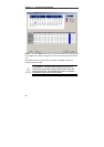
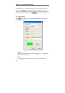
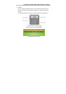
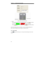
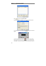
4. Test
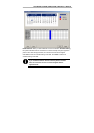
After installing the sensors, you can test the sensors immediately. Click
to find the sensor status: High electricity(Red) or Low electricity(Green).
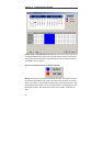
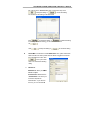
Click
to finish the setting or click to cancel the setting.