


122 Brocade BigIron RX Series Hardware Installation Guide
53-1002483-03
Software images required
6
NOTE
<xxxxx> is a variable that refers to the release-specific information as described in "Software Image
Naming Conventions". Specific contents of this field are determined by release and are described in
the relevant release notes.
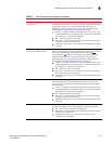
This section describes each of the software images required to operate a BigIron RX Series switch
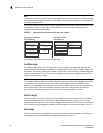
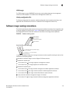
as described in Table 22. Also, Figure 47 illustrates how each of the files are stored on the
management and interface modules.
FIGURE 47 Management and interface modules flash images
The software images are described in the following:
IronWare image
An IronWare image, also known as the software image, contains the application software, the
network protocols and features that define the characteristics of the device. IronWare images can
be loaded in the Primary or Secondary location of Code Flash on the modules. IronWare images are
named as described in Table 22. There is one IronWare image for the management module and
another for the interface module.
NOTE
The IronWare image for interface modules is loaded on both the interface and managment modules.
The reason for this redundancy is to verify that the same image is loaded on all the interface
modules. The management module does not run the interface module code, it only compares the
code with the code on the other interface modules. If the code is not the same, the files are
synchronized and updated to match the interface code on the management module.
Monitor image
A Monitor image, also known as the real time operating system, allows hardware to run multiple,
parallel, distributed functions. The Monitor Image delegates low-level functions to the smaller
processor on each interface module. Monitor images are loaded in the Code Flash and Boot Flash
on the interface and management modules. Monitor images are named as described in Table 22.
Boot image
The Boot image, which is packaged with the Monitor image, contains initialization instructions for
the hardware startup. Boot images are named as described in Table 22.
Code Flash
Primary Ironware Image:
rmpr <xxxxx>
rIp <xxxxx>
Secondary Ironware Image:
rmpr <xxxxx>
rIp <xxxxx>
Boot Image:
rmb <xxxxx>
rIb <xxxxx>
FPGA Image:
mbridge
Boot Flash
Monitor Image:
rmb <xxxxx>
rIb <xxxxx>
Management Module
Flash Memory
Interface Module
Flash Memory
Code Flash
Primary Ironware Image:
rIp <xxxxx>
Secondary Ironware Image:
rIp <xxxxx>
Boot Image:
rIb <xxxxx>
Boot Flash
Monitor Image:
rIb <xxxxx>