


10 Brocade BigIron RX Series Hardware Installation Guide
53-1002483-03
Hardware features
1
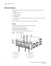
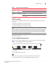
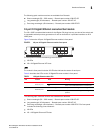
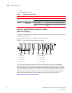
A two 10-Gigabit Ethernet module contains two physical ports, through which you can connect your
BigIron RX Series switch to other network devices at a speed of 10 Gigabits.
Into a physical port, you must insert a fiber-optic module provided by Brocade. The XFP-compliant
fiber-optic modules provide an optical transceiver or physical medium dependent (PMD) interface
for single mode fiber that can be used with the LAN physical layer (PHY).
The following optic modules versions are available from Brocade:
• Short wavelength (86 – 300 meters) – Brocade part number 10G-XFP-SR
• Long wavelength (10 kilometers) – Brocade part number 10G-XFP-LR
• Extra long wavelength (40 kilometers) – Brocade part number 10G-XFP-E=The front panel
includes the following control features:
• Eight LEDs
• Four 10 Gigabit Ethernet XFP slots
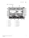
LEDs
The module’s front panel includes two LEDs that indicate the status of each port.
Table 3 describes the LEDs on the 10 Gigabit Ethernet module’s front panel.
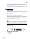
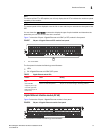
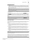
10 Gigabit Ethernet ports
A 10 Gigabit Ethernet module contain four physical ports, through which you can connect your
BigIron RX Series switch to other network devices at a speed of 10 Gigabits.
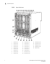
Into a physical port, you must insert a fiber optic module provided by Brocade. The XFP-compliant
fiber optic modules provide an optical transceiver or physical medium dependent (PMD) interface
for single mode fiber that can be used with the LAN physical layer (PHY).
TABLE 2 10 Gigabit Ethernet module LEDs
LED Position State Meaning
Link Left of each
Ethernet port
On A link is established with the remote port.
Off A link is not established with the remote port.
Active Left of each
Ethernet port
On or blinking The port is transmitting and receiving packets.
Off for an extended
period
The port is not transmitting or receiving
packets.
TABLE 3 10 Gigabit Ethernet module LEDs
LED Position State Meaning
Link Left of each
Ethernet port
On A link is established with the remote port.
Off A link is not established with the remote port.
Active Left of each
Ethernet port
On or blinking The port is transmitting and receiving packets.
Off for an extended
period
The port is not transmitting or receiving
packets.