


16 Brocade BigIron RX Series Hardware Installation Guide
53-1002483-03
Hardware features
1
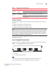
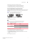
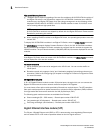
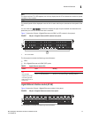
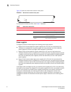
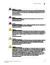
Figure 10 shows the switch fabric module’s front panel.
FIGURE 10 Switch fabric module front panel
The front panel includes two LEDs, which Table 7 describes.
Power supplies
The BigIron RX Series switches support the following power supply options:
• BigIron RX-4: Accommodates three power supplies (AC or DC) with one required and two
redundant. It is shipped with one power supply. You must purchase one or two additional
power supplies if you want your BigIron RX-4 equipped for redundancy.
• BigIron RX-8: Accommodates four power supplies (AC or DC) with two required and two
redundant. Because power is supplied over a common power bus, any power supply purchased
in addition to the two required will provide backup for any supply that fails. Equipping a BigIron
RX-8 with two additional power supplies provides full redundancy for both of the required
power supplies.
• BigIron RX-16: Accommodates eight power supplies (AC or DC) with four required and four
redundant. Because power is supplied over a common power bus, any power supply purchased
in addition to the four required will provide backup for any supply that fails. Equipping a BigIron
RX-16 with four additional power supplies provides full redundancy for all of the required power
supplies.
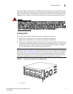
In the BigIron RX-8, and BigIron RX-16, you install the power supplies (AC or DC) in the slots along
the bottom of the chassis. In the BigIron RX-4, the power supplies (AC or DC) are installed in slots in
the rear of the chassis.The installed power supplies provide power to all chassis components,
sharing the workload equally and reporting their status to the management module. If the
management module detects that one of these power supplies has failed or overheated, the
management module will redistribute the failed power supply’s workload to the remaining power
supplies.
TABLE 7 Switch fabric module LEDs
LED Position State Meaning
Pwr Above Active LED On The module is receiving power.
Off The module is not receiving power.
Active Below Pwr LED On The chassis switch fabric is active and ready
to switch user packets.
Off for an extended
period
The chassis switch fabric is not active and
cannot switch user packets.
Pwr
Active
BI-SWF