


Page 12 MNNCEKRKB1_0439
Setup Description Example
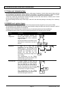
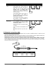
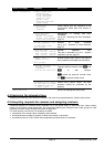
Devices in a
chain
The devices are connected in pairs
using single lines. These should be
terminated at the ends. This type of
setup can only be made when the
devices have a separate input
(reception) and output (transmission)
channel, like the Videotec DTRX1 and
DTRX3 receivers.
The received signal is sent “clean” to
the next device. If one device is
blocked, communication is cut off to the
devices later in the chain.
The maximum total length is equal to
the number of lines multiplied by
1200m for each distance.
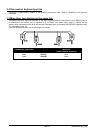
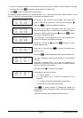
Mixed setup It is possible to set up mixed
configurations, always bearing in mind
the limits given above:
each line can have a maximum length
of 1200m
each line should be terminated at the
ends
the stubs should be very short (max.
2m)
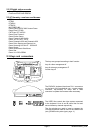
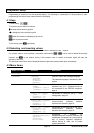
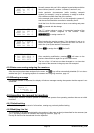
3.3 Standard connection cable
The connection between the EKR-KB1 keyboard and the various controlled devices is made only and
exclusively using a RS485 serial channel.
When the controlled device does not provide this channel it will be necessary to insert a signal converter (e.g.
RS486-RS232 or RS485- Current loop) between the keyboard and the device itself.
Connection with the latest generation of Videotec products (video switchers SM42A, SM82A, video matrix
SW328, EKR-8/4, EKR-16/4, etc.) can be made directly using a serial 1.5m telephone cable, which is supplied.
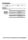
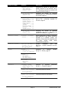
A pair of telephone cables with a pair of RJjack shunt boxes can be used to arrive at distances of up to 1200m
using the following connection diagram:
RJ
j
ack1 RJ
j
ack2
L=1200 m
EKR-KB1 RJjack 1 RJjack 2 Device
RS485A White Blue RS485A
RS485B Yellow Black RS485B