


8
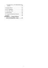
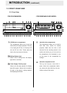
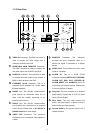
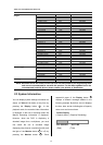
1.3.2 Rear View
RS-232
ALARM
DC12V
RS-485
AUDIO
IN
IN
OUT
OUT
VIDEO
TO
MONITOR
TO
MUX'S VCR IN
FROM MUX
MAIN MONITOR
ETHERNET
10/100
I/O
25 26 27 28 29 31
32 33
34 35 37 38 36
25
VIDEO IN Connector: This BNC connector is
used to connect the video output from a
camera or a MUX to the DVR.
26
FROM MUX MAIN MONITOR Connector:
This BNC connector is used to connect the
live video output from a MUX to the DVR.
27
AUDIO IN Connector: This connector is used
to connect the audio output from a camera, a
MUX or other devices to the DVR.
28
ETHERNET 10/100 Connector: This is a
standard RJ-45 connector for 10/100 Mbps
Ethernet networks.
29
RS-485 Port: The RS-485 communication
ports function as connectors when two or
more units are serially connected to an
external control device.
31
RS-232 Port: The RS-232 communication
port functions as a connector to an external
control device. Please refer to 6.1 RS-232 &
RS-485 Protocol for more details.
32
VIDEO OUT Connector: The connector
provides the unit’s composite video signals to
a MUX.
33
MONITOR Connector: The connector
provides the unit’s composite video or a
MUX’s live signal if connected to a display
device.
34
AUDIO OUT: This provides the unit’s audio
signal to a speaker.
35
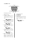
ALARM I/O: This is a 9-PIN D-SUB
connector including SWITCH OUT, GROUND,
ALARM OUT, DISK FULL, RECORD IN,
ALARM RESET, and ALARM IN points for
connecting with external devices. Please refer
to the next section for details.
36
Plug Inlet: The inlet connects to an external
power supply. Connect the 12 V DC UL-listed
Class 2 Power Supply.
37
Wire Catch: The wire catch secures the
power cord and keeps it in place (so that it
does not droop or hang loosely).
38
Ground Screw’s: The ground screw is for a
chassis terminal.