


ENGLISH
••••••••••••••••••••••••••••••••••••••••••••••••••••••••••••••••••••••••••••••••••••••••••••••••••••••••••••••••••••••••••••••••••••••••••••• Beginning
13
AUDIO IN
1
2
3
4
OUT
IN
AUDIO
CASCADE
AUDIO OUT
100-240V
AC IN~
MAX 350mA
DC 12V OUT
CLOCK ADJ
CLOCK ADJ OUT
REC
REC STOP
EMERGENCY
RESERVED
MODE OUT 1 +
+
MODE OUT 1 –
MODE OUT 2 +
+
MODE OUT 2 –
MODE OUT 3 +
+
MODE OUT 3 –
MODE OUT 4 +
+
MODE OUT 4 –
CALL OUT +
+
CALL OUT –
GND
GND
GND
GND
1
ALARM IN
2
3
4
5
6
7
8
9
10
11
12
13
14
15
16
RS485 TERM +
+
RS485 TERM –
P T Z
RS422
+
RS422
–
RS232
1
ALARM OUT
2
3
4
5
6
7
8
9
10
11
12
13
14
15
16
RS-232C
RS485RS485
INOUT
MAIN
OFF ON
RESET
OPTION SLOT
LAN-A LAN-B
STORAGE COM
SERIAL BUSSERIAL BUS
12345678
910111213141516
OUT
IN
CAMERA
OUT
IN
Y/C
OUTPUT B
CLAMPER
CLAMPER
OUTPUT A
VIDEO VIDEO
VIDEO CASCADE
INOUT
1010010100
13 15 16 1714
12
11
2
1
7
4563
108 9
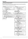
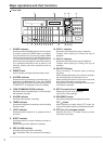
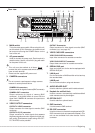
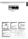
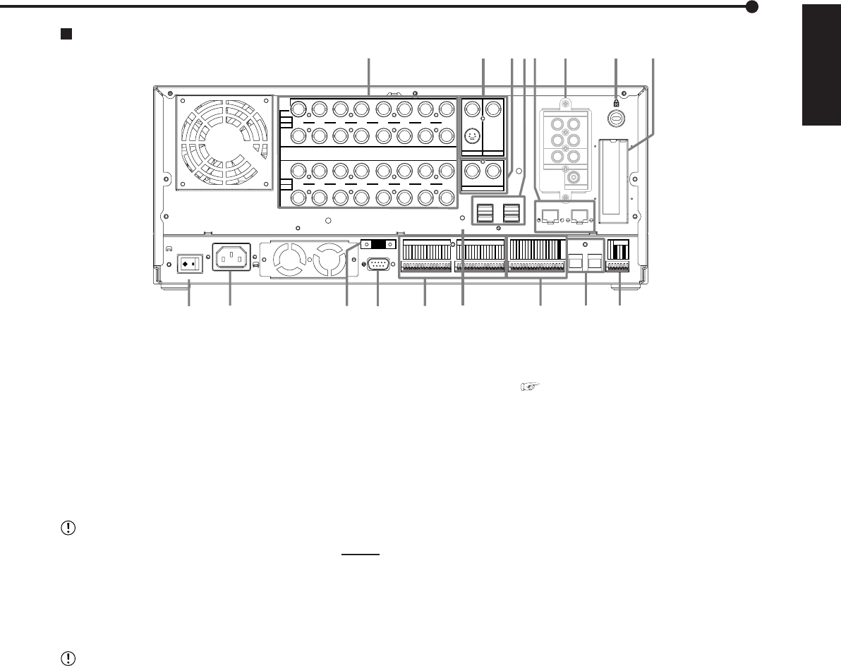
OUTPUT B connector
Output connector for video signal to monitor (BNC
connector) ( see page 16).
5. VIDEO CASCADE connectors
VIDEO CASCADE IN connector
Input video connector for cascade connection.
VIDEO CASCADE OUT connector
Output video connector for cascade connection.
6. SERIAL BUS port
Input and output port for the device equipped with
SERIAL BUS port.
7. LAN-A port
Port for connection of NAS hard disk unit to back up
the recorded data.
LAN-B port
Port for communication using web browser.
8. AUDIO BOARD SLOT
Used to attach an optional audio interface board.
9. Keyhole for antitheft lock
Used to connect a commercially available antitheft
cable manufactured by Kensington.
10. OPTION SLOT
Used to attach an optional board.
11. GND terminals
It is the common GND terminal.
12. RS-232C connector
Used to connect to a host device equipped with RS-
232C connector (such as a personal computer). This
unit can be controlled from other devices via this
connector.
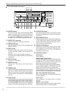
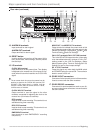
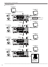
1. MAIN switch
This is the main power switch. When using this unit,
set this switch to ON. Otherwise, the power cannot
be turned on/off using the POWER button on the
front of the unit.
2. AC power socket
Used to connect the power cord. Earth terminal is
used for safety. Use the 100 to 240 V plug with earth
for the power of this unit.
• This unit must be earthed at all times. Never
connect this unit to a power outlet which does not
have an earth terminal.
• Please use the supplied AC power cord.
3. CAMERA connectors
• Do not connect superimposed voltage camera
because it causes product failure.
CAMERA IN connectors
Input connector for signal of camera (BNC connector).
CAMERA OUT connectors
Output connector for signal of camera (BNC
connector). If the MAIN switch is turned ON, the
signal from CAMERA IN connector is looped out to
this connector.
4. VIDEO OUTPUT connectors
OUTPUT A VIDEO connector
Output connector for video signal to monitor (BNC
connector).
OUTPUT A S(Y/C) connector
Output connector for video signals that separate
brightness signals and colour signals for higher pic-
ture quality. Simultaneous output along with OUT-
PUT A VIDEO is also possible.
Rear view