


20 3. TV Connections
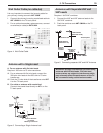
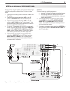
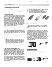
DVI Video Device (Cable Box, Satellite
Receiver, DVD Player, or Other Device)
Connect DVI devices (digital only) to the TV’s HDMI
input jacks.
Analog stereo audio cables and a DVI-to-HDMI cable or
DVI/HDMI adapter and HDMI cable are required.
1. Connect the DVI-to-HDMI cable (recommended) or
HDMI cable with DVI/HDMI adapter from the DVI
device’s back panel to the TV’s HDMI jack.
Note: If you are using a DVI/HDMI adapter, it is impor-
tant to connect the adapter to the DVI device for
best performance.
2. Connect a set of audio cables from
AUDIO OUT
on the DVI device back panel to the
DVI/PC AUDIO
INPUT
on the TV back panel. Connect the red
cable to the
R
jack and the white cable to the
L
(MONO)
jack.
Note: The HDMI connection supports copy protection
(HDCP).
Some devices require connecting to an analog
input first, in order to view on-screen menus
and to select DVI as the ouput. Please review
your equipment instructions for DVI connectivity
and compatibility.
3
-
"6%*0065
%7*065
COMPONENT 1
Y Pb Pr (480i/480p/720p/1080i)
COMPONENT 2
RECORD
OUTPUT
OUTPUT
DIGITAL
IR EMITTER
NetCommand
RS-232C
ANT 1 /
MAIN
ANT 2 /
AUX
AUDIO
INPUT 1
INPUT 2
HDMI
VIDEO: 480i / 480p / 720p /
1080i / 1080p
W-SVGA, XGA, W-XGA,
AUDIO: LINEAR PCM
PC: VGA, W-VGA, SVGA,
1
(LEFT) ,, 2 (MIDDLE) 3 (RIGHT)
DVI / PC
VIDEO
AUDIO-
AUDIO-
RIGHT
LEFT
L (MONO)
INPUT
AVR
AUDIO
AUDIO
OUTPUT
S-VIDEO VIDEO - AUDIO - R
L (MONO)
- AUDIO - R
Y Pb Pr
EMITTER
3D GLASSES
SXGA / 720p / 1080p
IEEE 1394
DVI / PC
INPUT
AUDIO
%7*UP)%.*
$BCMF
%7*%FWJDF
57#BDL1BOFM
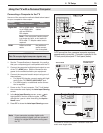
Figure 8. Connecting a digital DVI device
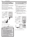
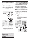
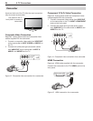
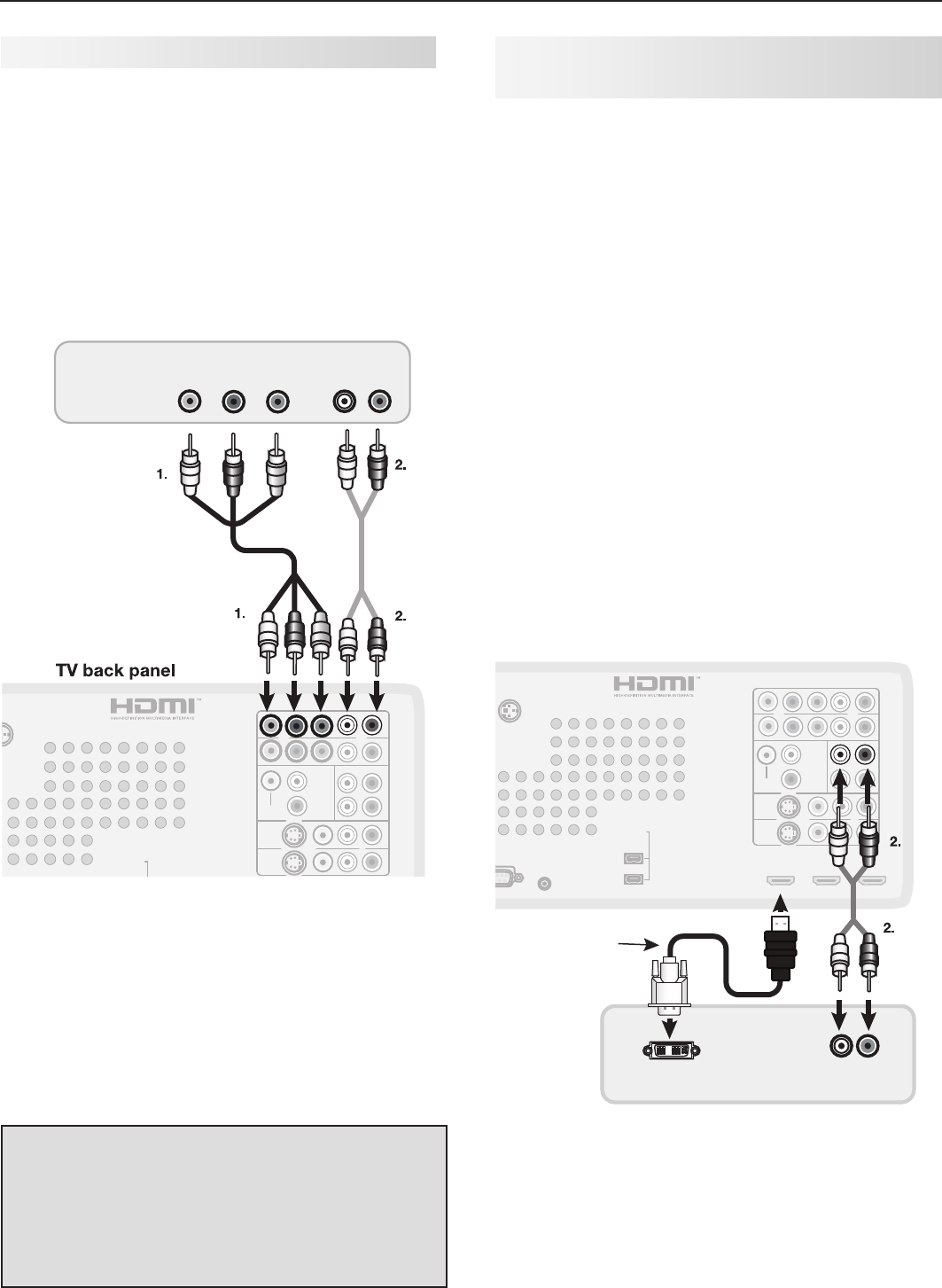
DVD Player with Component Video
Component video cables and analog audio cables are
required.
1. Connect the component video cables from
Y Pb Pr
VIDEO OUT
on the back of the DVD player to the
COMPONENT
jacks on the TV back panel, match-
ing the green, blue, and red colored connections.
2. Connect left (white) and right (red) stereo audio
cables from
AUDIO OUT
on the back of the DVD
player to
COMPONENT AUDIO L (MONO)
and
AUDIO
R
on the TV back panel.
COMPONENT 1
Y Pb Pr (480i/480p/720p/1080i)
COMPONENT 2
RECORD
OUTPUT
OUTPUT
DIGITAL
IR EMITTER
NetCommand
RS-232C
ANT 1 /
MAIN
ANT 2 /
AUX
AUDIO
INPUT 1
INPUT 2
HDMI
VIDEO: 480i / 480p / 720p /
1080i / 1080p
W-SVGA, XGA, W-XGA,
AUDIO: LINEAR PCM
PC: VGA, W-VGA, SVGA,
1 (LEFT) ,,2 (MIDDLE) 3 (RIGHT)
DVI / PC
VIDEO
AUDIO-
AUDIO-
RIGHT
LEFT
L (MONO)
INPUT
AVR
AUDIO
AUDIO
OUTPUT
S-VIDEO VIDEO - AUDIO - R
L (MONO)
- AUDIO - R
Y Pb Pr
EMITTER
3D GLASSES
SXGA / 720p / 1080p
IEEE 1394
COMPONENT 1
$0.10/&/57*%&0
"6%*0065
- 3
:
1C
1S
%7%1MBZFS
Figure 7. Connecting a DVD player with component
video
Note:
To hear digital surround sound from your DVD
player, connect the digital audio output from the
DVD player directly to your digital A/V receiver.
IMPORTANT
See Appendix A for component video signal
compatibility information.
For digital audio connections to your A/V
receiver, see your DVD player and A/V receiver
Owner’s Guides.