


3. TV Connections 23
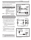
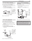
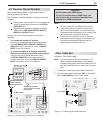
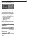
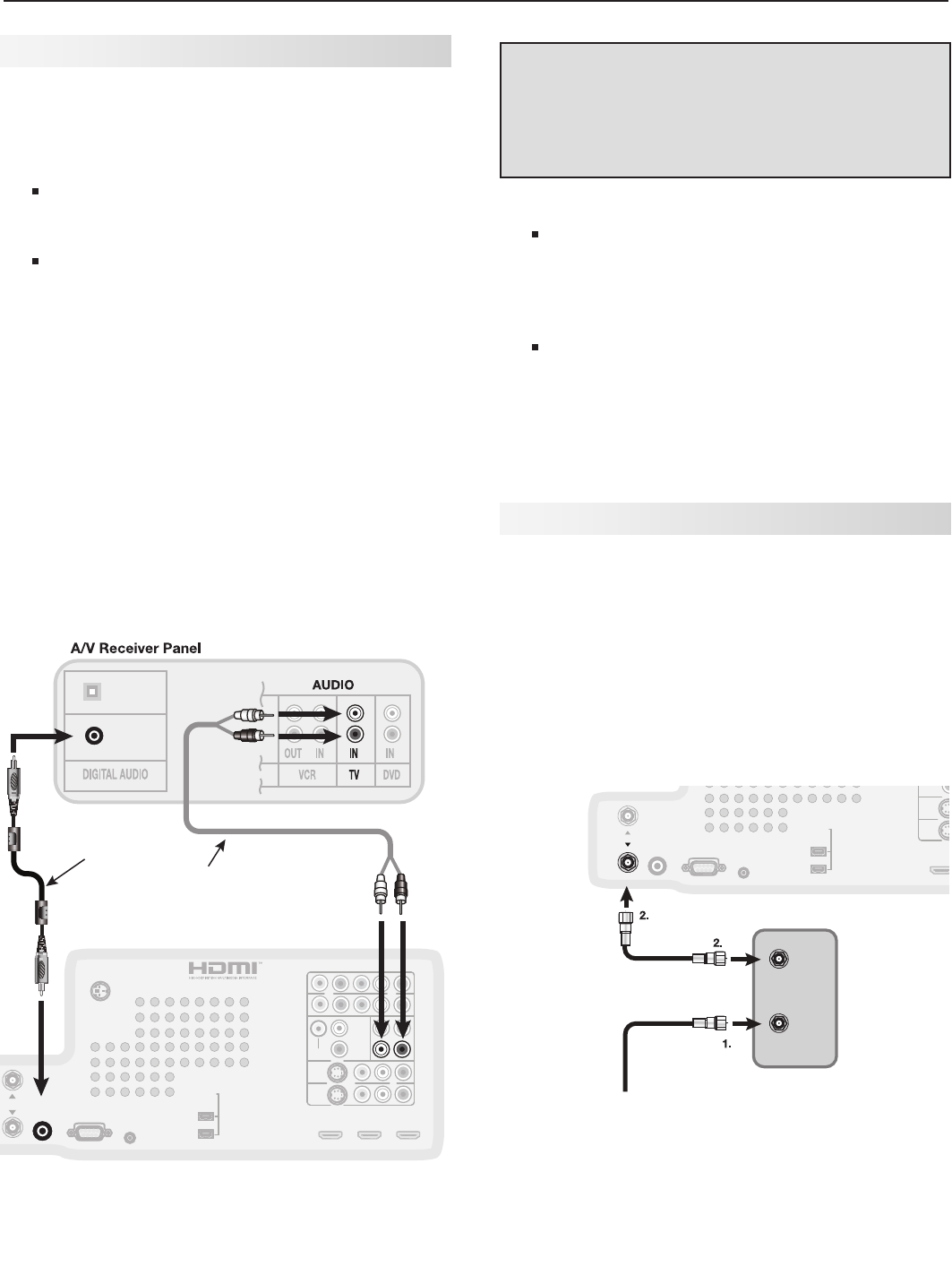
Older Cable Box
Required: One coaxial cable.
Note: This connection is not recommended. The
other connections described in this chapter
provide better quality audio and video to the TV
and allow NetCommand to work with the cable
box.
1. Connect the incoming cable to
IN
on cable box.
2. Connect one coaxial cable from
OUT
on the cable
box to
ANT 1/MAIN
on the TV back panel.
COMPONENT 1
Y Pb Pr (480i/480p/720p/1080i)
COMPONENT 2
RECORD
OUTPUT
OUTPUT
DIGITAL
IR EMITTER
NetCommand
RS-232C
AUDIO
INPUT 1
INPUT 2
HDMI
VIDEO: 480i / 480p / 720p /
1080i / 1080p
W-SVGA, XGA, W-XGA,
AUDIO: LINEAR PCM
PC: VGA, W-VGA, SVGA,
1
(LEFT) ,,2 (MIDDLE) 3 (RIGHT)
DVI / PC
VIDEO
AUDIO-
AUDIO-
RIGHT
LEFT
L (MONO)
INPUT
AVR
AUDIO
AUDIO
OUTPUT
S-VIDEO VIDEO - AUDIO - R
L (MONO)
- AUDIO - R
Y Pb Pr
EMITTER
3D GLASSES
SXGA / 720p / 1080p
IEEE 1394
ANT 2 / AUX
ANT 1 / MAINANT 1 / MAIN
065
*/
$BCMF#PY
*ODPNJOH
$BCMF
5P"/5."*/
57#BDL1BOFM
Figure 12. Connecting an older cable box
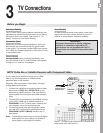
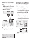
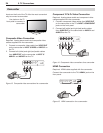
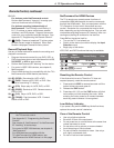
A/V Receiver (Sound System)
Most setups require either a digital audio cable or
analog stereo audio cables.
The TV makes all audio available in digital and analog
formats:
Analog audio coming into the TV is available as
output in digital stereo format on the
DIGITAL
AUDIO OUT
jack.
Digital incoming audio is available as analog
output on the
AVR AUDIO OUTPUT
/
AUDIO L
(MONO)
and
AUDIO R
jacks.
Usually, only one of the following connections is
required:
• To connect an analog A/V receiver
Connect left (white) and right (red) audio cables
from
AVR AUDIO OUTPUT
/
AUDIO L (MONO)
and
AUDIO R
on the TV back panel to the
TV AUDIO
INPUT
on the A/V receiver.
• To connect a digital A/V receiver with Dolby
Digital surround sound and PCM audio support:
Connect one end of the digital audio cable
to
DIGITAL AUDIO OUT
on the back of the TV.
Connect the other end to the
COAXIAL DIGITAL
INPUT
on the back of the A/V receiver.
$0"9*"-
*/165
015*$"-
*/165
$0"9*"-
*/165
COMPONENT 1
Y Pb Pr (480i/480p/720p/1080i)
COMPONENT 2
RECORD
OUTPUT
OUTPUT
DIGITAL
IR EMITTER
NetCommand
RS-232C
AUDIO
INPUT 1
INPUT 2
HDMI
VIDEO: 480i / 480p / 720p /
1080i / 1080p
W-SVGA, XGA, W-XGA,
AUDIO: LINEAR PCM
PC: VGA, W-VGA, SVGA,
1 (LEFT) ,,2 (MIDDLE) 3 (RIGHT)
DVI / PC
VIDEO
AUDIO-
AUDIO-
RIGHT
LEFT
L (MONO)
INPUT
AVR
AUDIO
AUDIO
OUTPUT
S-VIDEO VIDEO - AUDIO - R
L (MONO)
- AUDIO - R
Y Pb Pr
EMITTER
3D GLASSES
SXGA / 720p / 1080p
IEEE 1394
ANT 2 / AUX
ANT 1 / MAIN
OUTPUT
DIGITAL
AUDIO
AVR
AUDIO
OUTPUT
%JHJUBM$PBYJBM$BCMF
6TFUPDPOOFDUB
EJHJUBM"7SFDFJWFS
4UFSFP"OBMPH$BCMFT
6TFUPDPOOFDUBOBOBMPH
"7SFDFJWFS
57#BDL1BOFM
Figure 11. Connecting the TV to an A/V receiver
Important
A/V Receivers with HDMI Inputs
If your A/V receiver has an HDMI input, use
one of the audio connections described here
instead of an HDMI connection.
Note:
On rare occasions, an HDMI signal may be
copy-restricted and cannot be output from
the TV as a digital signal. To hear these copy-
protected signals through the A/V receiver, use
connections for analog A/V receivers.
Check the A/V receiver’s Owner’s Guide for
information concerning use of the digital input
and switching between digital sound and
analog stereo sound from the TV.