


22 3. TV Connections
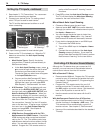
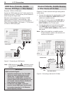
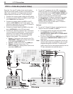
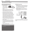
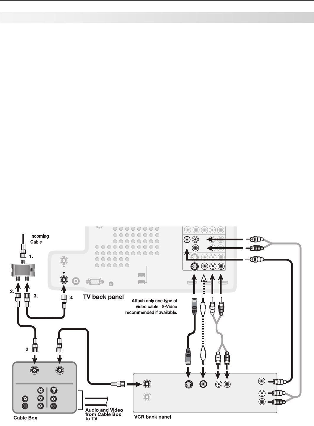
Figure 10. Connecting a VCR to a cable box
065
7*%&0
065
7*%&0
*/
*ODPNJOH
$BCMF
"6%*0
065
"6%*0
*/
*/
"/5&//"
-
-
3
3
3
-
$"#-&
065
*/
:
1C
1S
3
-
3
-
"6%*0
47*%&0
COMPONENT 1
Y Pb Pr (480i/480p/720p/1080i)
COMPONENT 2
RECORD
OUTPUT
OUTPUT
DIGITAL
IR EMITTER
NetCommand
RS-232C
AUDIO
INPUT 1
INPUT 2
HDMI
VIDEO: 480i / 480p / 720p /
1080i / 1080p
W-SVGA, XGA, W-XGA,
AUDIO: LINEAR PCM
PC: VGA, W-VGA, SVGA,
1
(LEFT)
,, 2
(MIDDLE)
3
(RIGHT)
DVI / PC
VIDEO
AUDIO-
AUDIO-
RIGHT
LEFT
L (MONO)
INPUT
AVR
AUDIO
AUDIO
OUTPUT
S-VIDEO VIDEO - AUDIO - R
L (MONO)
- AUDIO - R
Y Pb Pr
EMITTER
3D GLASSES
SXGA / 720p / 1080p
IEEE 1394
ANT 2 / AUX
ANT 1 / MAI
N
RECORD
OUTPUT
AUDIO-
AUDIO-
RIGHT
INPUT 2
L (MONO)
S-VIDEO VIDEO - AUDIO - R
LEFT
ANT 1 / MAIN
*/
065
065
B
B
C
C
VCR to a Cable Box (Audio & Video)
Required: Two-way RF splitter, three coaxial cables,
right and left audio cables, S-Video or composite video
cable, plus component or S-Video cables and audio
cables required to connect the TV to the cable box.
1. Connect the incoming cable to
IN
on the RF splitter.
2. Connect one coaxial cable from
OUT
on the RF split-
ter to
CABLE IN
on the cable box.
3. Connect one coaxial cable from
OUT
on the RF
splitter to
ANT 1/MAIN
on the TV back panel. This
connection also allows you to use the TV Guide On
Screen and Split Screen features.
4. Connect one coaxial cable from
OUT
on the cable
box to
ANTENNA IN
on the VCR back panel.
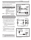
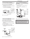
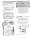
5. Connect the cable box outputs to the TV as shown
in one of the options listed below. This connection
allows the TV to receive the best available signal
directly from the cable box. See the referenced
figures in this chapter, “TV Connections.”
• Figure 1: Component video output to the TV’s
COMPONENT Y Pb Pr
jacks; analog stereo audio
to the associated
AUDIO
jacks.
• Figure 2: HDMI output to the TV’s
HDMI
jack.
• Figure 3: S-Video output to the TV’s
INPUT S-VIDEO
jack; analog stereo audio to the
associated
AUDIO
jacks.
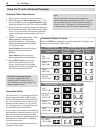
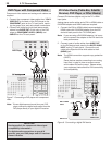
6. To use the TV speakers with the VCR, connect left
(white) and right (red) audio cables from
AUDIO OUT
on the VCR back panel to
INPUT AUDIO L (MONO)
and
R
on the TV back panel. If your VCR is mono (non-
stereo), connect only the white (left) cable.
7. Connect either an S-Video or composite video cable
from
VIDEO OUT
on the VCR back panel to
INPUT/
VIDEO
or
INPUT S-VIDEO
on the TV back panel.
Connect only one type of video cable. S-Video is
recommended, if available.
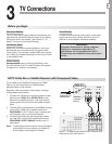
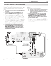
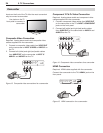
Optional
8. To use the TV Guide On Screen recording feature to
record to the VCR from
ANT 1
or
ANT
2
:
a. Connect left (white) and right (red) audio cables
from
AUDIO IN
on the VCR back panel to
RECORD OUTPUT/
AUDIO LEFT
and
AUDIO RIGHT
on the TV back panel.
b. Connect a video cable from
VIDEO IN
on the VCR
back panel to
RECORD OUTPUT VIDEO
on the TV
back panel.
Note:
When using this connection configuration with the con-
nections used in step 5, it is possible to view live cable
programs through the VCR Device. For best picture
quality always view live cable programs directly from the
TV input connected to the cable box device.